Tweets
Replying to @josecastillo
…if I can find just two spare red/green LED’s in my parts bin, that’ll be an even 400 Sensor Watch boards for this shipment to Crowd Supply. To think: in just three hours of rework, we got that number up from 376, and it wasn’t even that painful in the end! This was a good day.
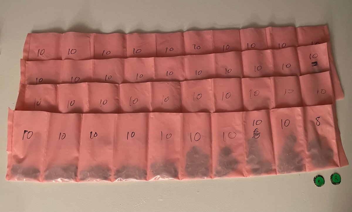
(original)
Replying to @josecastillo
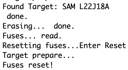
well that was a freebie. +2; 398 boards. The thirs one accepts the bootloader now, but is still acting temperamental when it comes to running the tests. still I don’t care that much, because…
(original)
Replying to @josecastillo
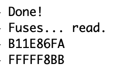
fetched a known good user row from one of the other 396 boards
(original)
Replying to @jgerity
That was the recommendation that sent me to this one! Definitely planning on reading it after this one :)
(original)
Replying to @audreydodgen
It was such a cool place to visit!
(original)
Replying to @josecastillo
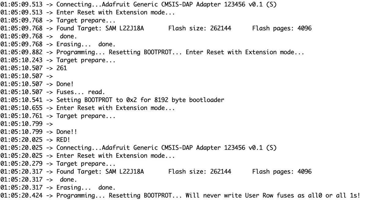
alas, still nothing, but an interesting hint: my programming tool IS successfully connecting to these boards, but the fuses in the user row seem to be shot. I bet this is a software fix: if I can reset the fuses to a known good value, maybe I can rescue these three boards.
(original)
Replying to @josecastillo
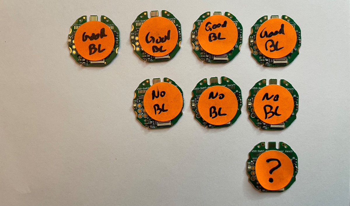
trying the same procedure on two of the boards marked “No BL”, not that the crystal should have any effect at that stage. but the caps do look like they’re a bit too cozy, and I don’t see any other obvious defect on visual inspection…
(original)
Replying to @josecastillo
+4; 396 boards.
(original)
Replying to @josecastillo
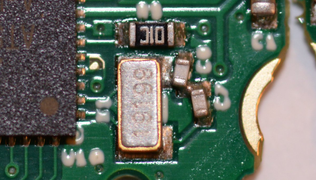
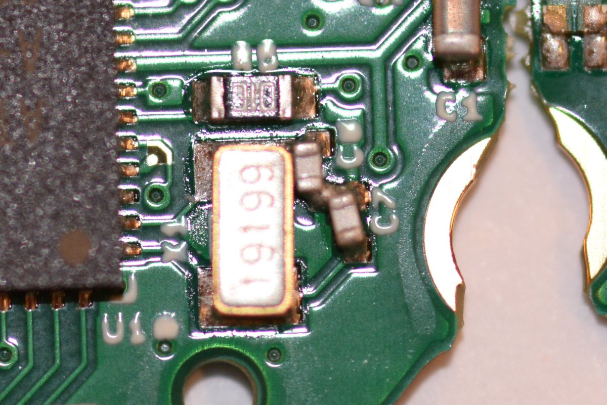
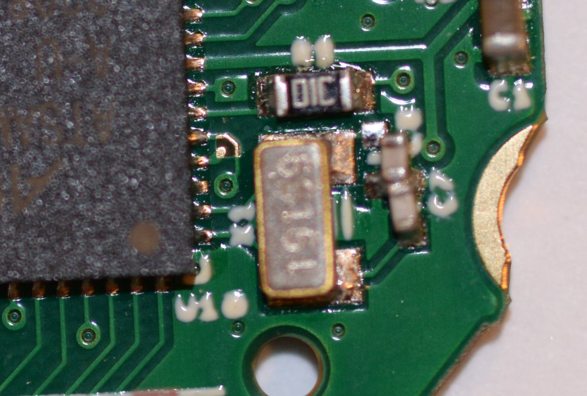
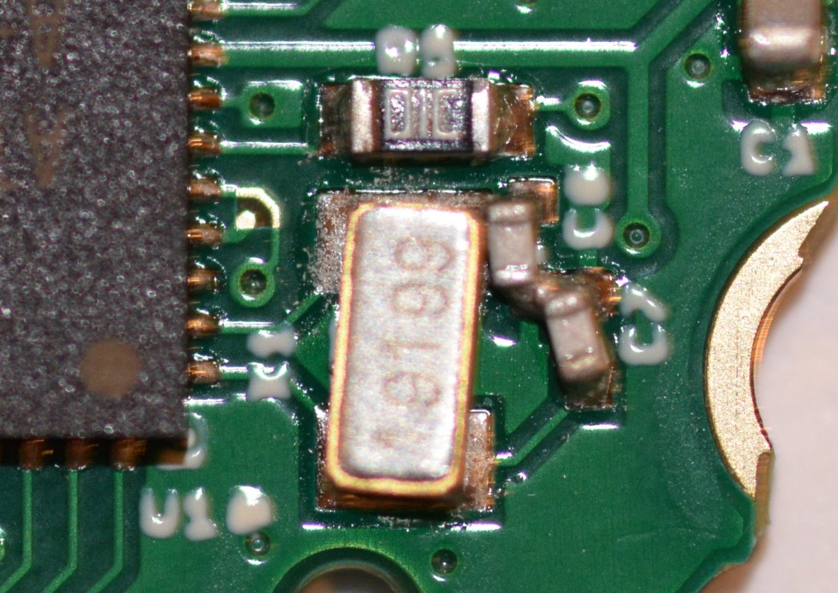
the four boards marked “Good Bootloader” have one thing in common: original sin. (my term for my questionable capacitor layout near the crystal). Even as we speak I’m warming up the hot plate; I sense that a scooch of C6 will set these boards back on the straight and narrow.
(original)
Replying to @josecastillo
anyway, +1; 392 boards.
(original)
Replying to @josecastillo
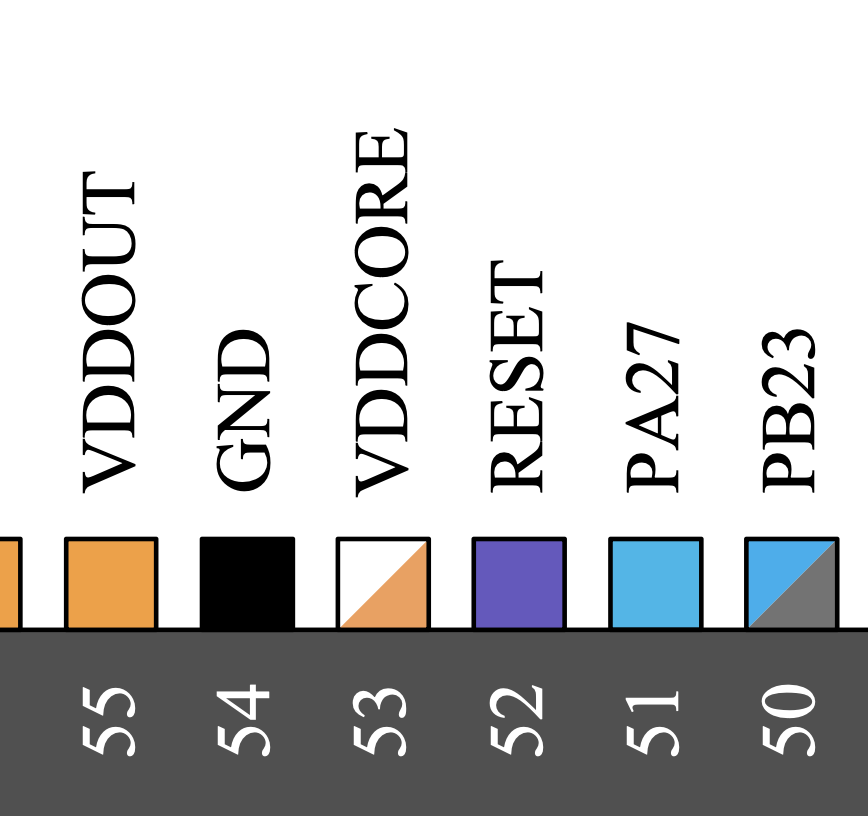
I should have taken a picture, but I fixed it too quickly: solder bridge between PA27 and Reset. PA27 is the buzzer. Which means the buzzer was going low to make a beeping sound, resetting the board, which pulled it high again, until it tried to buzz, which reset the board…
(original)
Replying to @josecastillo
Hah ok figured out ?’s malfunction. Its failure mode: flashes the bootloader fine, but in test #2, the buzzer repeatedly makes clicking noises and the whole device acts generally glitchy.
(original)
Replying to @josecastillo
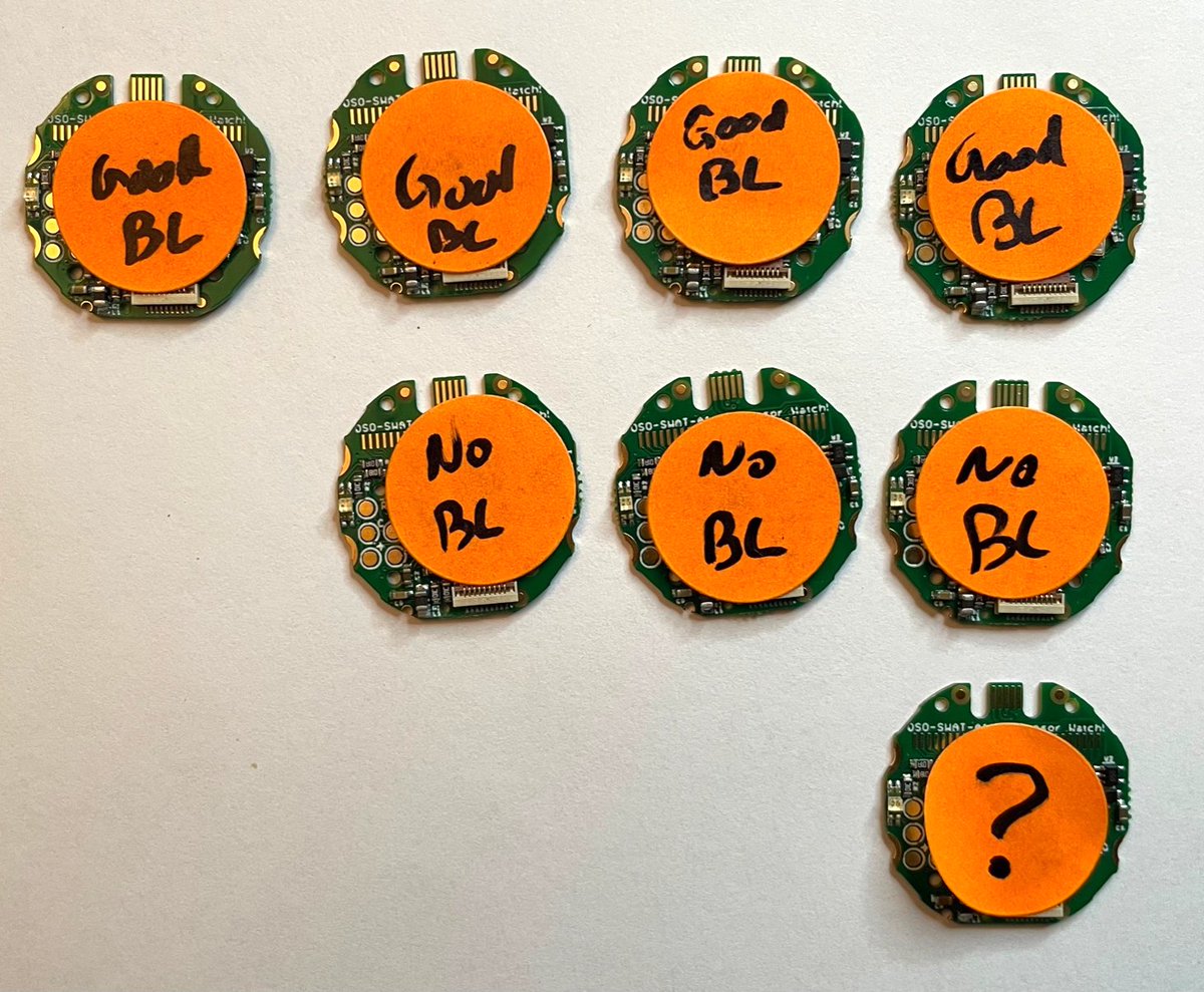
this brings us to the eight boards I couldn’t diagnose earlier, which honestly I may get to tomorrow. The categories are “Good BL”, where the bootloader flashed but no tests would run, “No BL”, where the bootloader wouldn’t flash, and “?” which failed test #2 in a really odd way.
(original)
Replying to @josecastillo
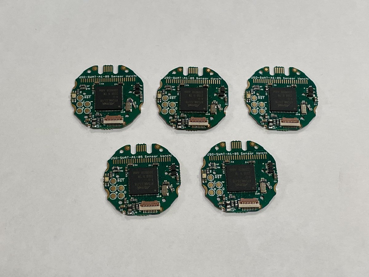
+5 more; 391 boards.
(original)
Replying to @robojeep
It’s on me for designing it that way, honestly; if I ever do a rev 2, I’ll need to rethink that corner of the board. Thanks for watching out for them!
(original)
Replying to @josecastillo
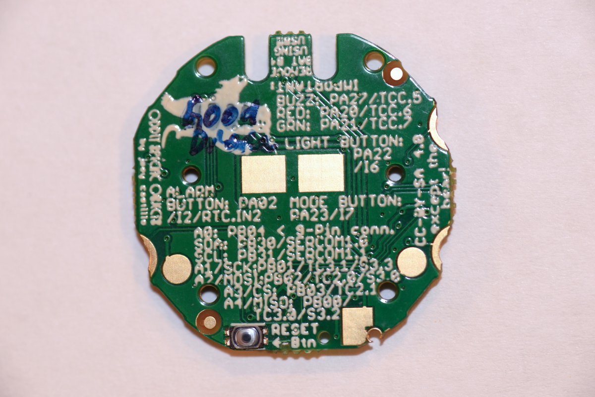
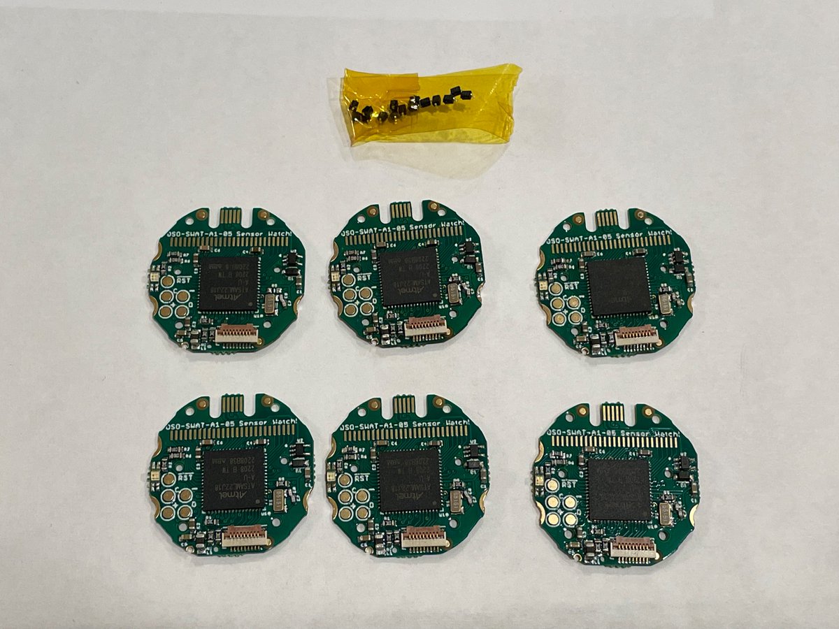
and oh look: past-Joey already did one while testing last month! One of you is going to get a board with “Good Diode” written on the bear, and I promise you that means it’s extra good. +1; 386 boards.
(original)
Replying to @josecastillo
also thankfully: @robojeep suggested that he include a few of the correct diode in the box with my boards. Brings a whole new meaning to “cut tape”! Anyway, all I have to do is hot plate and swap the good diode onto these boards, and I’ll have six more.
(original)
Replying to @josecastillo
This brings us to the boards whose failure mode was my hubris. I swapped a diode due to part shortage drama, and it didn’t go as well as hoped. Thankfully @MakeAugusta did a test panel last month, and we caught it in the first 10, of which I still have 6… https://twitter.com/josecastillo/status/1544082742987612160
(original)
Replying to @josecastillo
…add the tiniest smear of flux, and reheat the two pins. The bridge vanishes in a puff of smoke. +5; 385 boards.
(original)
Replying to @josecastillo
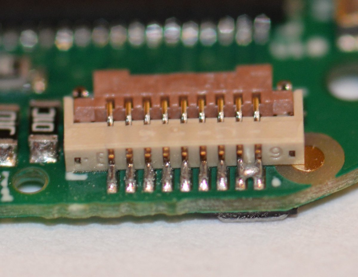
Then of course there’s the big one, whose failure mode I won’t demonstrate since it involved drawing enough current to make my lights flicker. We think we have a handle on what was causing this consistent solder bridge between the 9-pin’s VCC and GND. Luckily it’s an easy fix…
(original)
Replying to @josecastillo
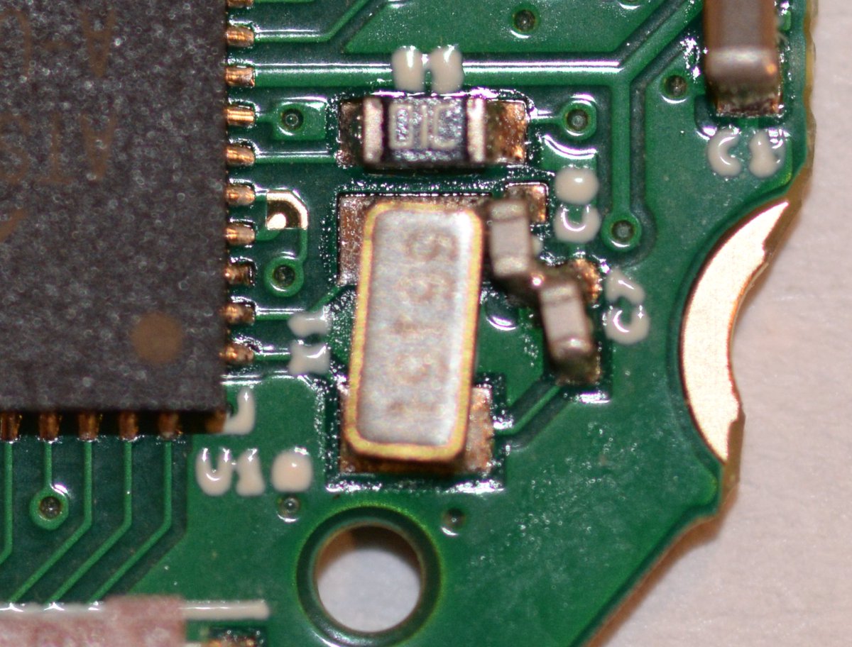
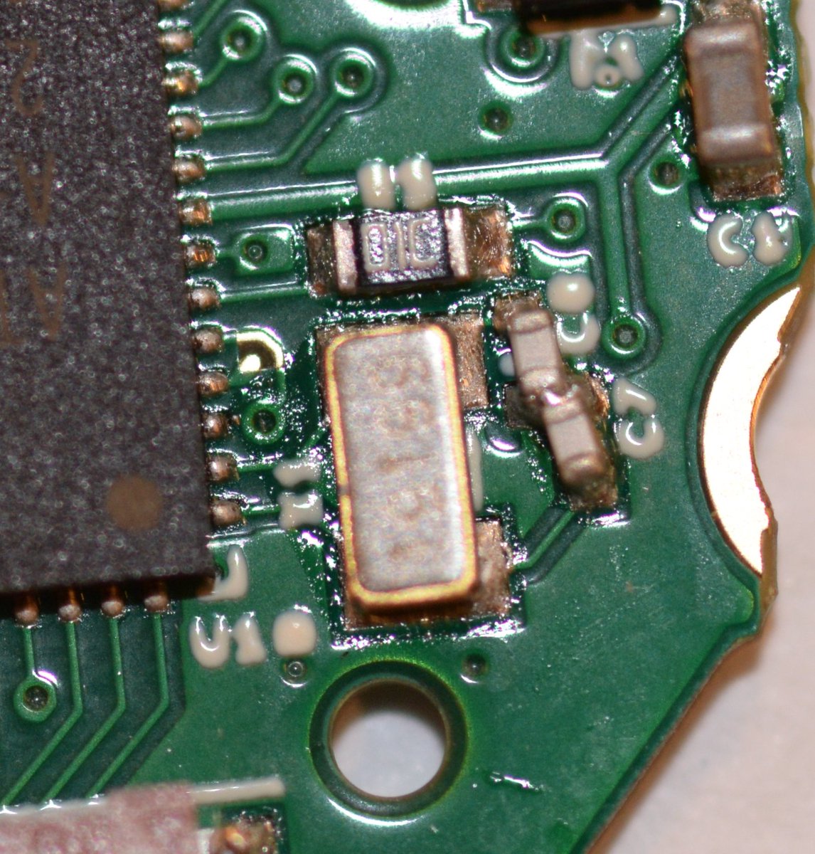
This is the original sin of this board: 0402 capacitor C8 is way too close to the crystal, and sometimes they want to get a little closer. This shorts one side of the crystal to GND, and obviously prevents it from ticking. Same drill: hot plate, +1, 380 boards.
(original)
Replying to @josecastillo
The real-time clock gets tested in the last step, the green test. It should tick red and green at half-second intervals, but I’ve seen this failure before: if the crystal doesn’t start oscillating, the RTC will be stuck at 0:00:00, and it’ll only show red.
(original)
Replying to @josecastillo
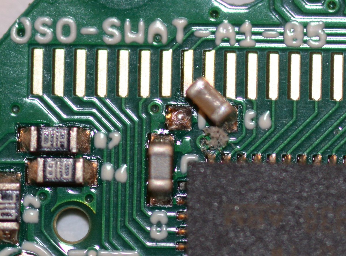
So yeah, that would do it. That capacitor is supposed to connect to VLCD, the output for the LCD driver’s charge pump. needless to say the LCD driver is unlikely to work well without it. Quick trip to the hot plate and we’re back in business. +1; 379 boards.
(original)
Replying to @josecastillo
This one was super puzzling: nothing at all on the display, but otherwise all tests working fine. Hadn’t seen it before. Didn’t know what to think. But then I looked at the board…
(original)
Replying to @josecastillo
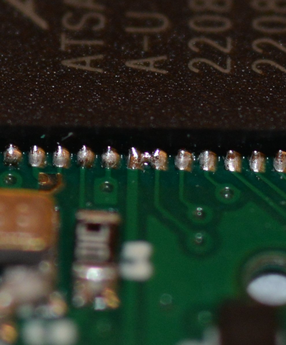
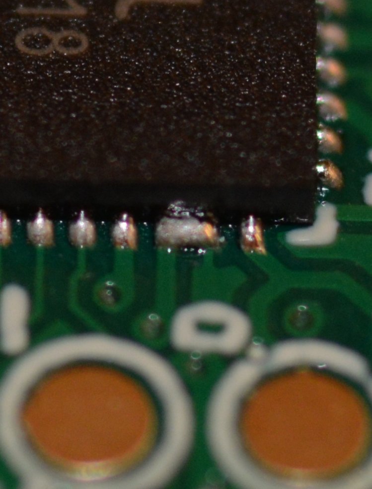
The culprit: a tiny solder bridge connecting one of the LCD pins to GND. On further inspection I also found a bridge between a USB data line and GND, which would have manifested as a USB failure eventually. Anyway, hand-reflow with a soldering iron will fix it up. +1; 378 boards.
(original)
Replying to @josecastillo
Next: LCD failure. This one manifests when the LCD test pattern presents incorrectly. In this case you can see lots of segments are sort of half-lit, whereas the display is mostly supposed to say “uuuuu”.
(original)
Replying to @josecastillo
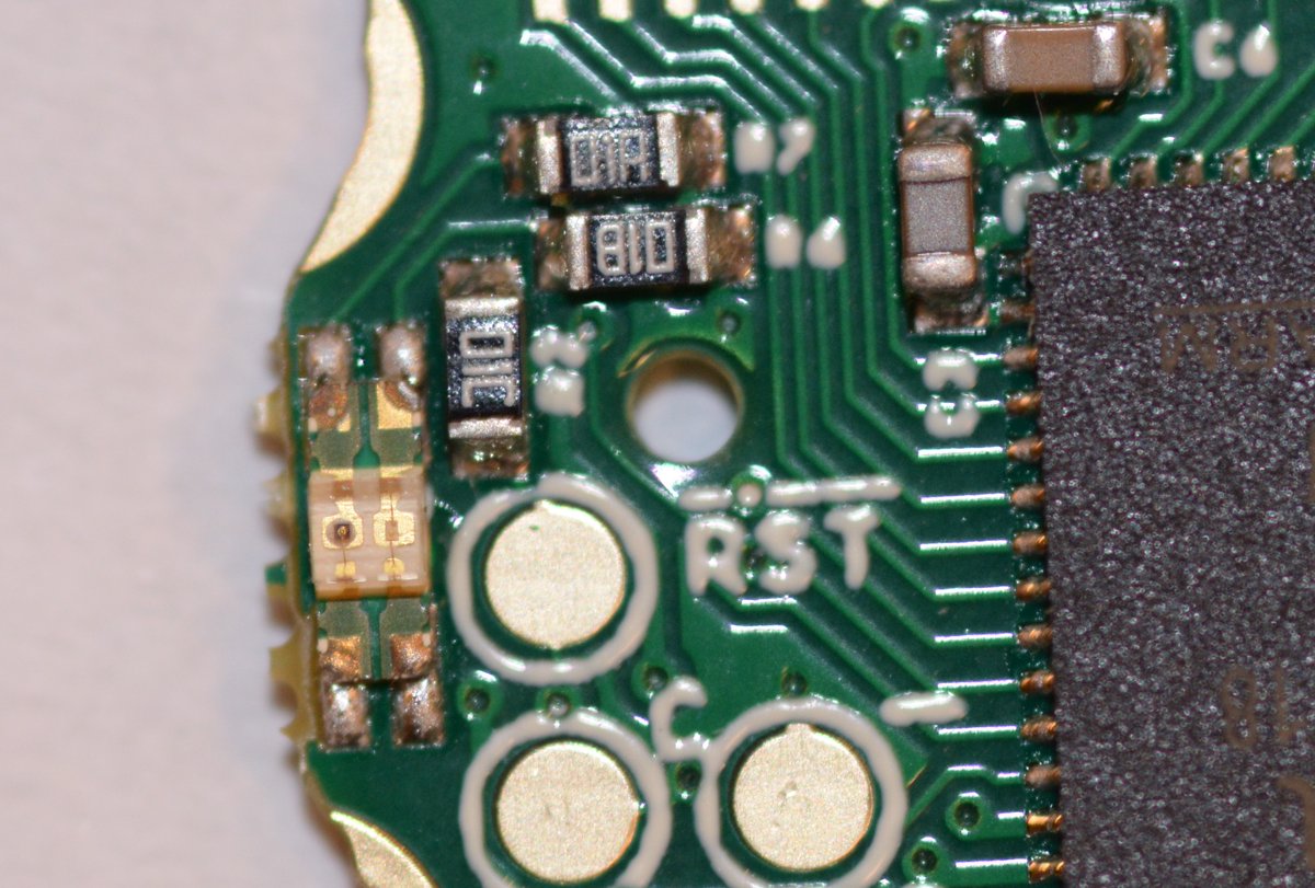
Alas, I don’t see anything wrong here, and hitting the red LED with my diode tester yields no light. I think this might just be a dud of an LED? Anyway if I can find a spare in my parts bag, I can fix it. For now, +0; still 377 boards.
(original)
Replying to @josecastillo
Next up: red LED failure. This almost looks like a DOA board since it doesn’t flash the red bootloader LED on test #1, the red button. But moving onto test #2 shows that it’s just the LED that’s dead; the board itself is alive and well, just missing red and yellow lights.
(original)
Replying to @josecastillo
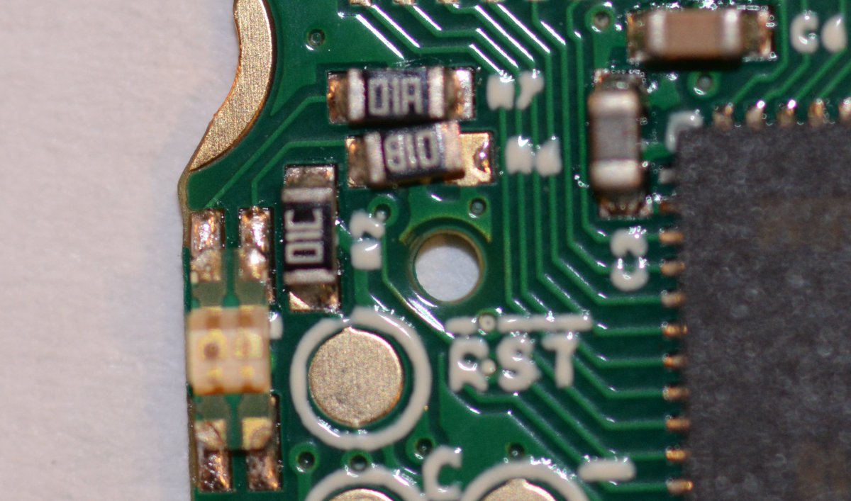
The culprit: R6, and a little bit of missing solder paste. This is preventing the green LED’s current limiting resistor from connecting to ground; a dab of solder with the soldering iron should fix it right up. +1; 377 boards.
(original)
Replying to @josecastillo
first up, the low hanging fruit: LED failures. One board’s green LED failed to light up. That manifests in test #2, the yellow button. In that test, contacts touching the three buttons trigger three colors, and you can tell it failed because both green and yellow fail to show up.
(original)
Replying to @josecastillo
OK! Ready. But before I begin I just want to point out that no manufacturing process is 100%. Moreso when it’s a compact & fiddly design like Sensor Watch. I expected some QA failures. Point is they’re diagnosable and documentable, and things we can fix. So let’s do those things.
(original)
RT @ajbauer: It’s not fascism unless it’s from the fasc region of Italy. Everything else is just an “anti-democracy experiment.” https://t.…
(original)
Replying to @josecastillo
A quick run; then dinner and then rework. Getting to 390 should be easy peasy.
(original)
Replying to @josecastillo
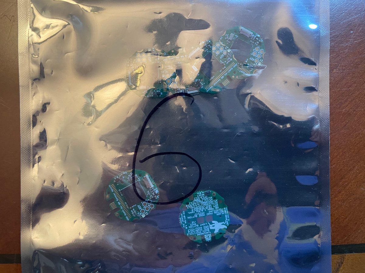
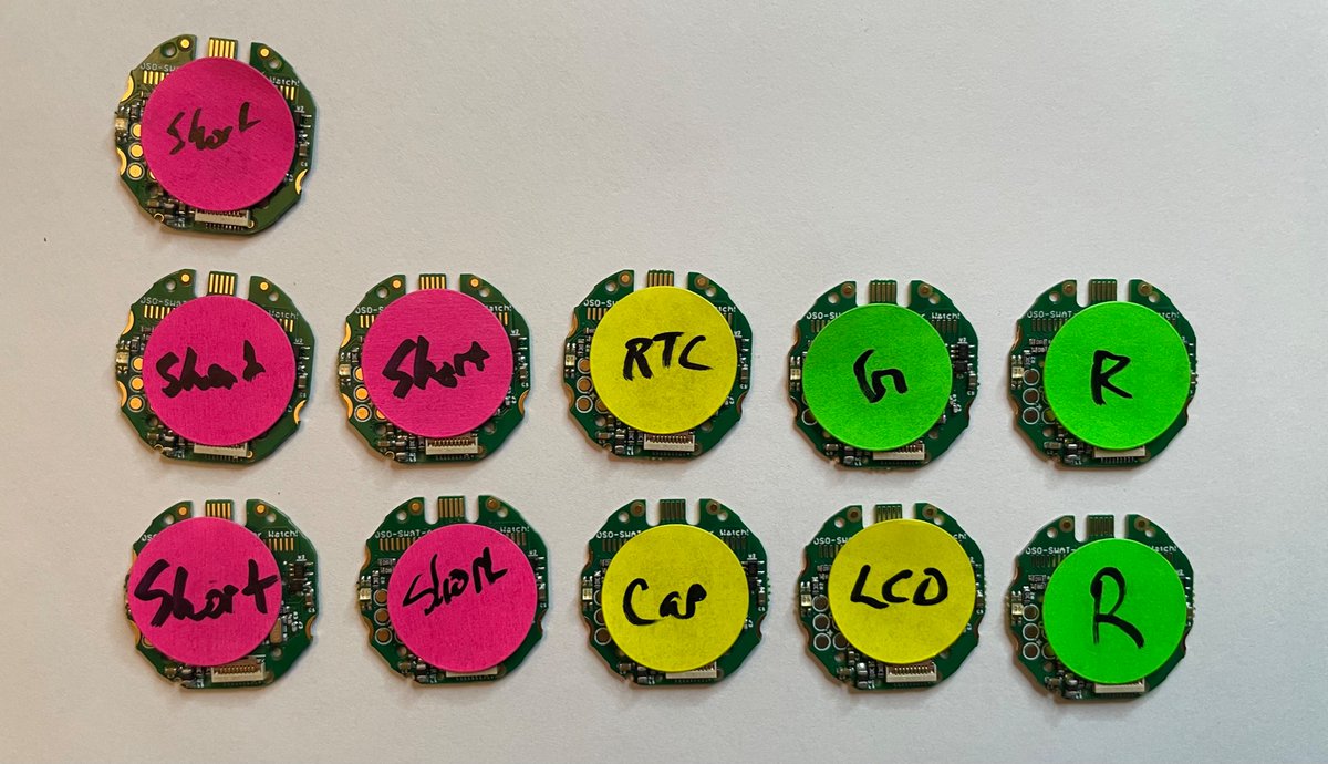
The state of play:
376 working, first try
+6 leftover from a diode snafu
+11 needing minor rework
+8 needing more diagnosis
≈401 boards, hopefully?
I feel pretty good about this. In a moment of extreme parts shortage, this shipment will fulfill most of our backers right on time.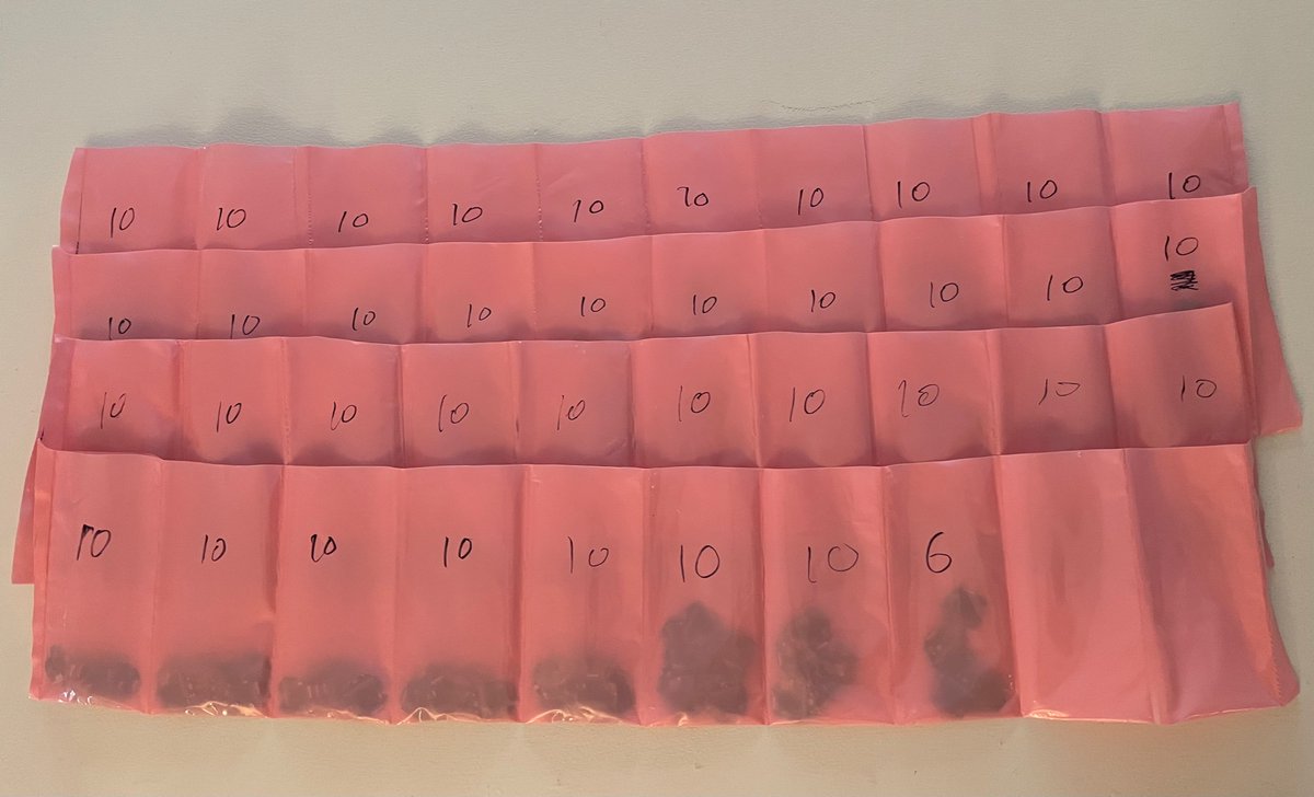
(original)
Replying to @josecastillo
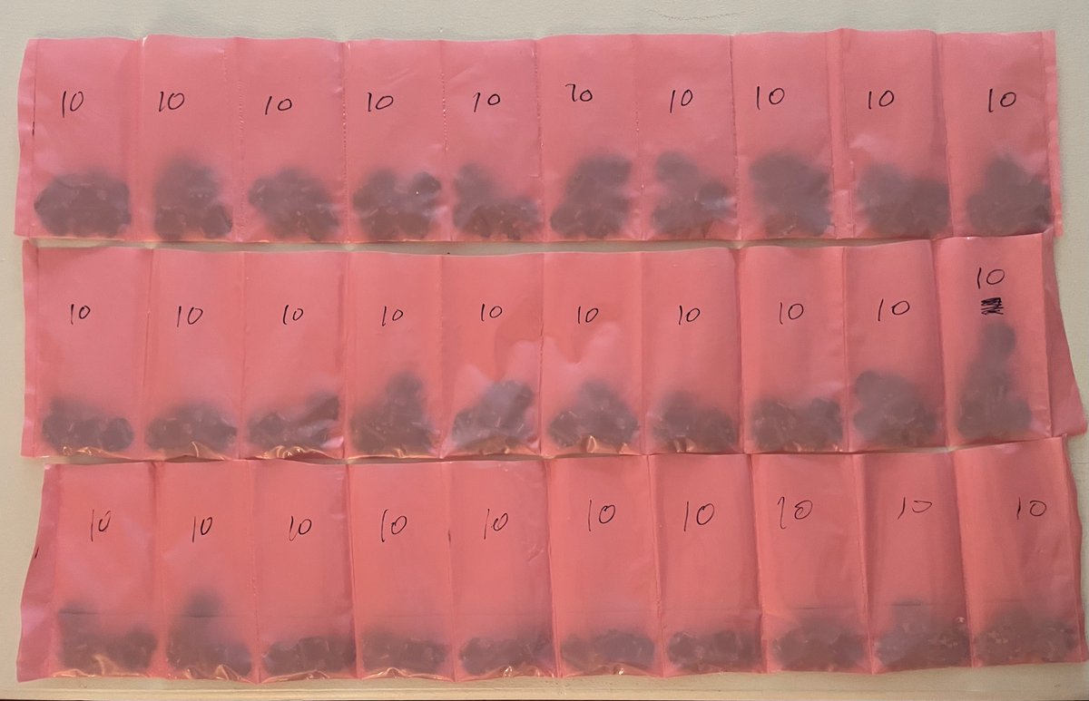
300 down.
(original)
Replying to @MakeAugusta
not definitive, but I’m noticing that the three boards with this issue have no mouse bites on the right, indicating that they were originally on the right side of the panel. Less FR-4 nearby leading to uneven heating maybe?
(original)
Replying to @MakeAugusta
I’ll find out about the other pins when I do the 9-pin connector test, which is step 2 of 3, probably next weekend. FWIW this seems to be pretty rare; it’s only affected three out of almost 300 tested so far.
(original)
Replying to @josecastillo
How much current must my USB hub have been passing to make the connector shield hot like a hot plate? I don’t know, but from now on I’m double checking this first. 🙂
(original)
Replying to @josecastillo
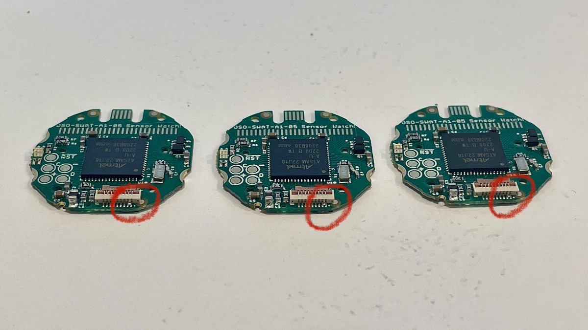
On the plus side, I’ve discovered the issue with three of my boards. On the minus side, I discovered it when my USB ring light started to flicker and I burned a finger: that’s a bridge between the VCC and GND pins on the 9-pin connector. (another plus: it’s an easy thing to fix.)
(original)
Replying to @josecastillo
roughly 200 down; roughly 200 to go. Got my technique down last night; once everything is depaneled and sanded, I can do a board every 20 seconds if the tester cooperates. 🤞🏽
(original)
Replying to @AlperenAkkuncu
Sandpaper! The only way to panelize round PCBs like mine is with tabs, but even after breaking them off, I have to do a little light sanding of the leftover mouse bites to make sure it fits in the Casio watch enclosure.
(original)
Replying to @MakerBlock
Ah I wish! Alas my flashing process requires full attention. This is just sanding the top and bottom mouse bites when the boards are still in a row of five, instead of depaneling fully and doing the boards one by one.
(original)
Replying to @josecastillo
I read for a bit; now back to it, and folks: I have figured out the best step in my process to sand the edges off my circuit boards. Add that to the list of things I didn’t know I’d need to know when I came up with this gadget.
(original)
Replying to @MakeAugusta
Two won’t accept the bootloader. One takes the bootloader, but test programs don’t run. On visual inspection I suspect the crystal load caps — in hindsight, I definitely put them too close together — but I plan to test everything first and do any required rework once that’s done.
(original)
Replying to @theavalkyrie
This is just staggeringly cool 🤩
(original)
Replying to @josecastillo
post-dinner I’m torn between doing another 100 boards, and reading a book. (last night I started “A Fire Upon the Deep” by Vernor Vinge and it’s been hard to put down)
(original)
Replying to @twilliability and @EdgeImpulse
Hard to overstate how strongly I recommend @EdgeImpulse! Check out this thread, where I dump some jogging data as CSV files & ingest it into my ML model. Train it online, and then export your on-device classifier directly as C++ code or an Arduino library. https://mobile.twitter.com/josecastillo/status/1495531421666103300
(original)
Replying to @MicroPhonon and @MakeAugusta
In this case I asked them to send me the raw panels, just because I know my test procedure is kind of a headache. At the time I started doing this my firmware flasher was a PyRuler + DuPont connectors; it would take some work to turn my process into something workable for others.
(original)
Replying to @justAfanDavid, @PCBWayOfficial, @MouserElec, @digikey and @MakeAugusta
I think you’ll do great! With the exception of the buzzer tweak, it’s all screwdriver oriented work; it’s no different really than swapping the battery on an F-91W.
(original)
Replying to @twilliability
I did it all with @EdgeImpulse! Tho I never ended up publishing the work; my year was spent largely on getting the watch and the wing built, and unless/until I have accelerometer sensor boards made, it felt a bit ‘castles in the sky’ to share something that only runs on my wrist.
(original)