Tweets
Replying to @josecastillo
rerouting…
(original)
Replying to @twopoint718
Not quite capacitive (no cap touch on the RP2040) but I’m thinking an elastomeric pad someday, the kind with little conductive bits on the bottom: https://twitter.com/josecastillo/status/1546168088995012609
(original)
Replying to @josecastillo
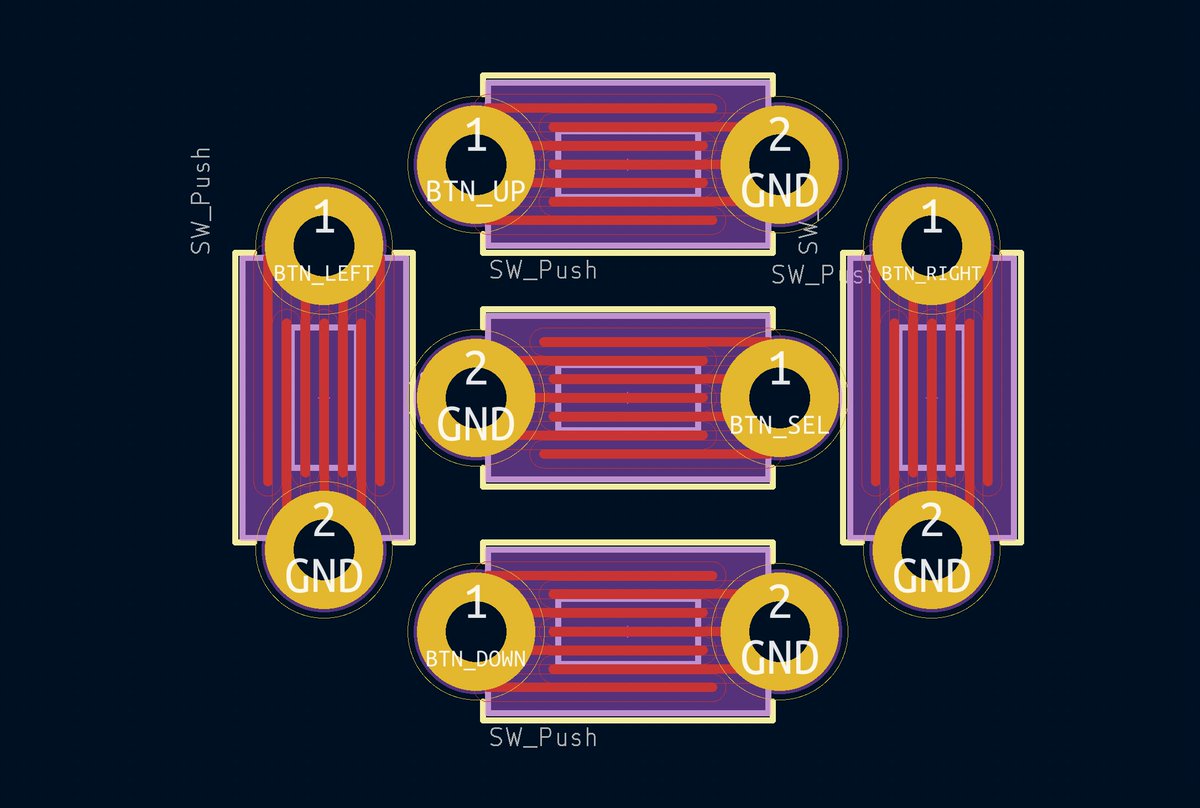
Right now I’m not ready for it; I think this DIY route is going to be the way we get the tech in folks’ hands quick. Which is why it’s a hybrid footprint: it’s the same through hole buttons, this hypothetical future plan will just get hidden underneath once they’re soldered down.
(original)
Replying to @josecastillo
It would absolutely require some kind of enclosure to hold the elastomeric pad in place. But then again, 3D print farms allow for low volume manufacturing, and if we wanted to make 10000 of these someday, injection molding exists. Remember, say it with me: “Anything can be made.”
(original)
Replying to @josecastillo
and get this: they’re cheap. Like, if I could have a custom liquid crystal display fabricated for a thing, surely I can have a floppy piece of rubber made. There’ll likely be a MOQ, but say the MOQ is 5000. That’s, like, doable if they cost a dime a piece. https://www.alibaba.com/product-detail/Silicone-Keypads-Keypad-Remote-Control-Standard_1600415070387.html
(original)
Replying to @josecastillo
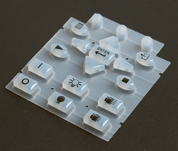
There’s another technology that can press buttons. You see it in inexpensive devices like pocket calculators and remote controls. It’s called an elastomeric keypad, and it’s basically a floppy piece of rubber molded with button shapes, and a conductive contact under each one.
(original)
Replying to @josecastillo
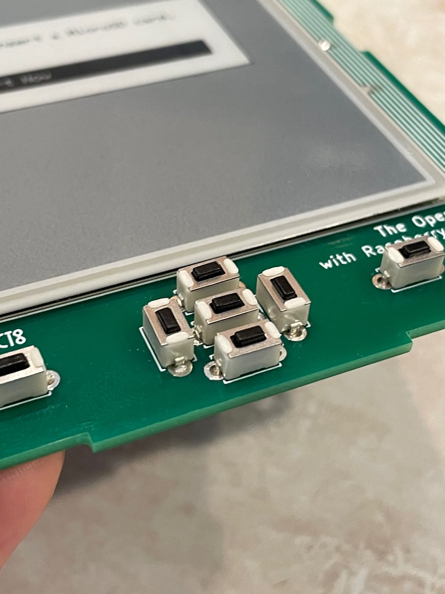
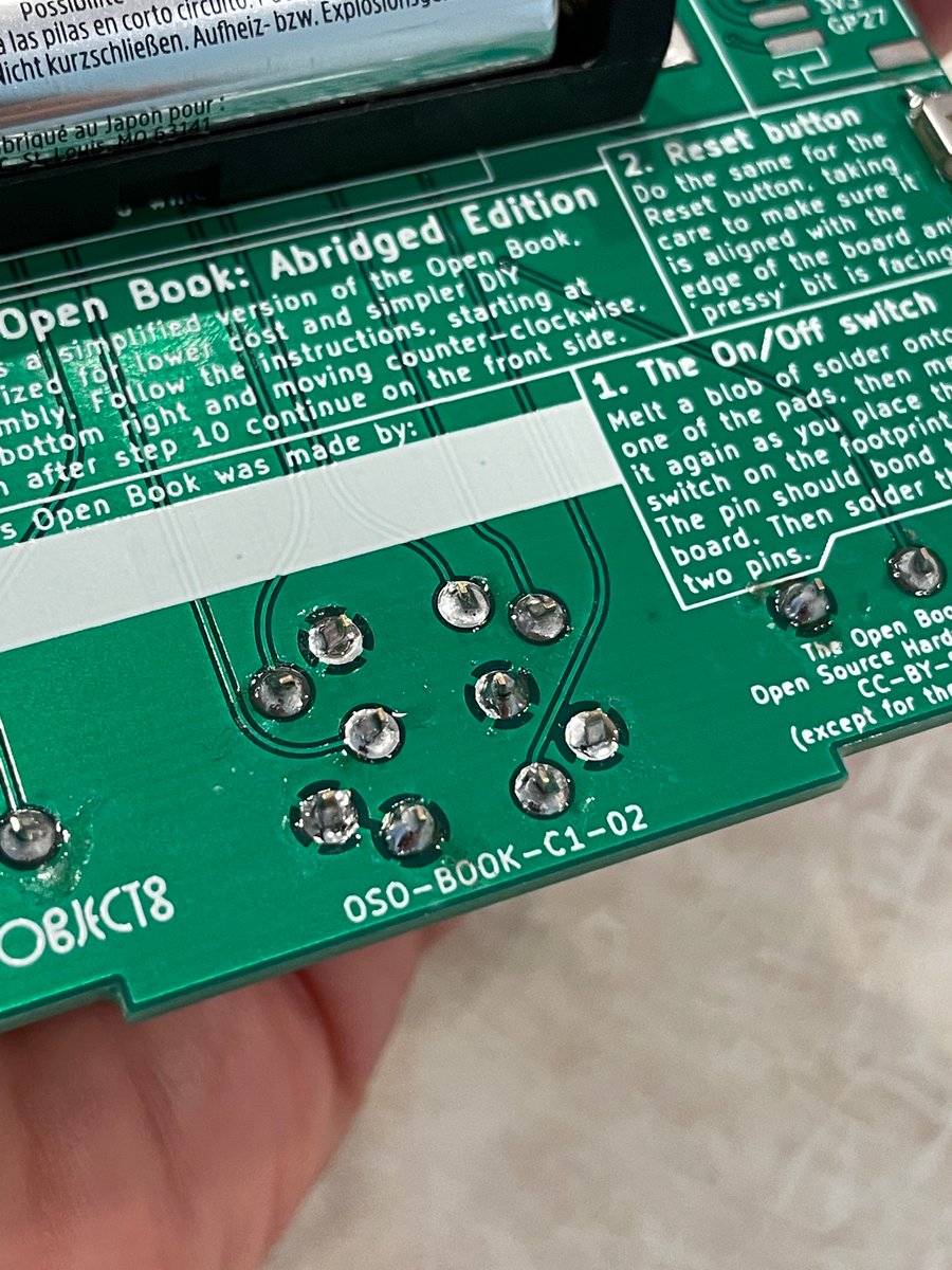
which brings us back to that pattern under the buttons. Right now, those buttons are through-hole parts. Ideal for DIY soldering: they’ll be placed perfectly and soldered securely. They also add $2 to the BOM cost, and likely additional manufacturing cost if we went that route.
(original)
Replying to @josecastillo
what’s more, if I was willing to commit to a minimum order quantity — in this case just 1,000 — I could make it affordably enough to launch a product with it and get it into hundreds of people’s hands. “Anything can be made.” 4/?
(original)
Replying to @josecastillo
I dipped my toes into a new medium when I designed a custom LCD this year, which was rad: I realized that with the skills I had learned, I could ask someone to use glass and twisted nematic fluid to bring a custom liquid crystal display into the world. 3/? https://twitter.com/josecastillo/status/1539324633589157888
(original)
Replying to @josecastillo
the sudden accessibility of PCB design in recent years made me feel empowered to build gadgets; I became confident that I could lay out a board, ask someone to fabricate it, and bring that object into being. but it does feel kind of arbriatry to stop at fiberglass and copper. 2/?
(original)
Replying to @josecastillo
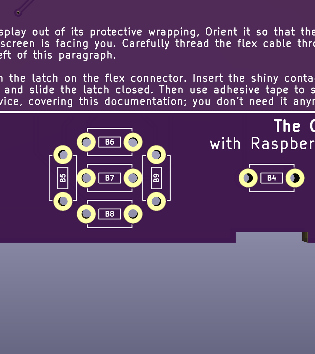
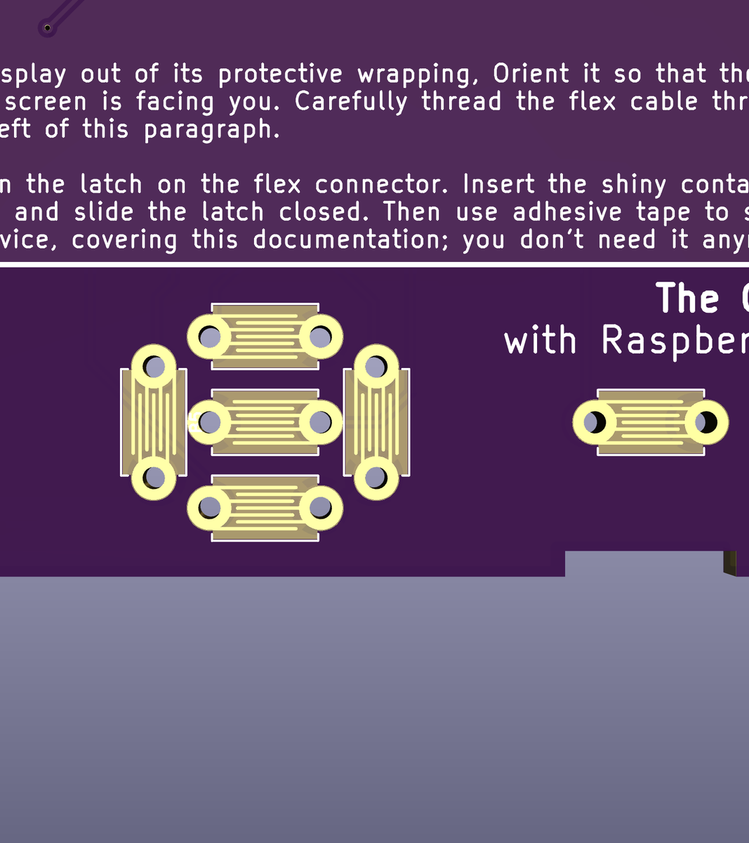
ok. this is weird I admit. but it stems from a conversation I was having with my shopmates back in New York. Talking about the design of an ATM at a bar, a phrase floated across the table: “Anything can be made.” it’s been stuck in my head ever since, like a koan or a mantra. 1/?
(original)
Replying to @josecastillo
at this point I think we are pretty much set, pending rerouting all the traces we broke. still there is one more change I want to make. requires a little thought though. also breakfast. The thrilling conclusion, after some yogurt.
(original)
Replying to @josecastillo
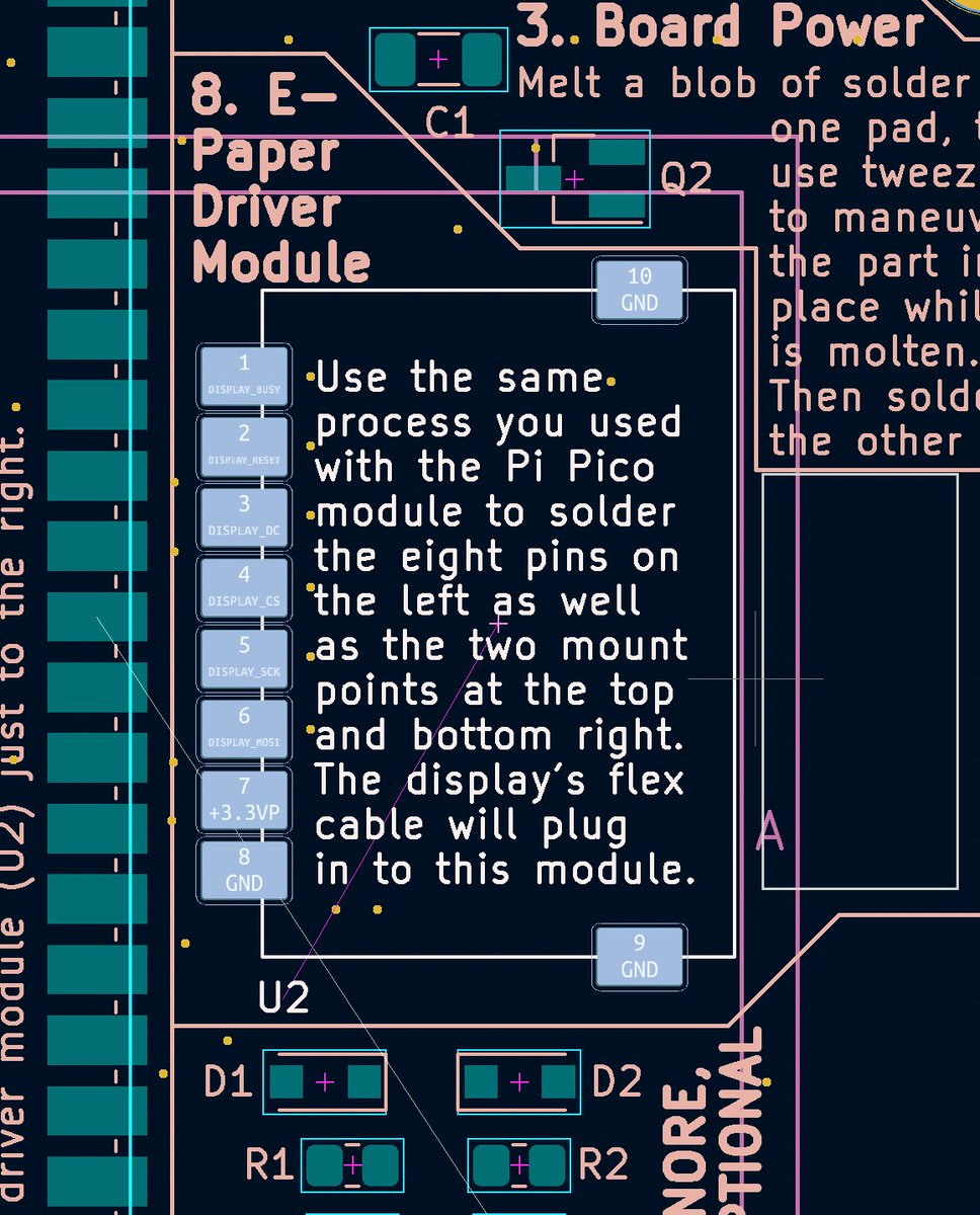
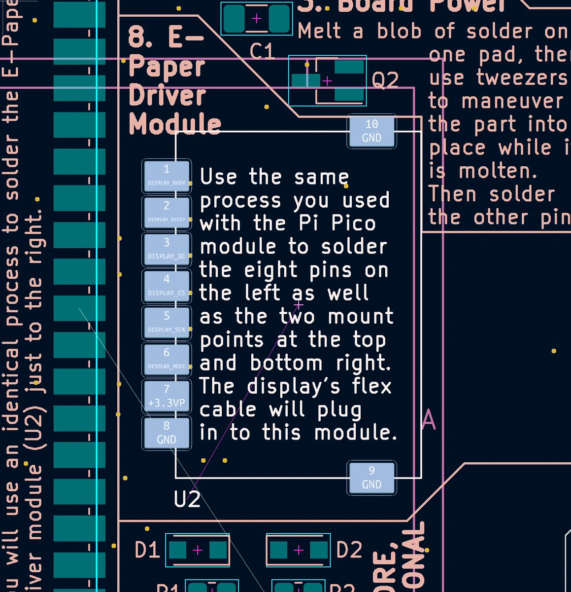
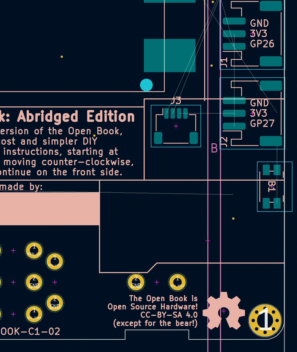
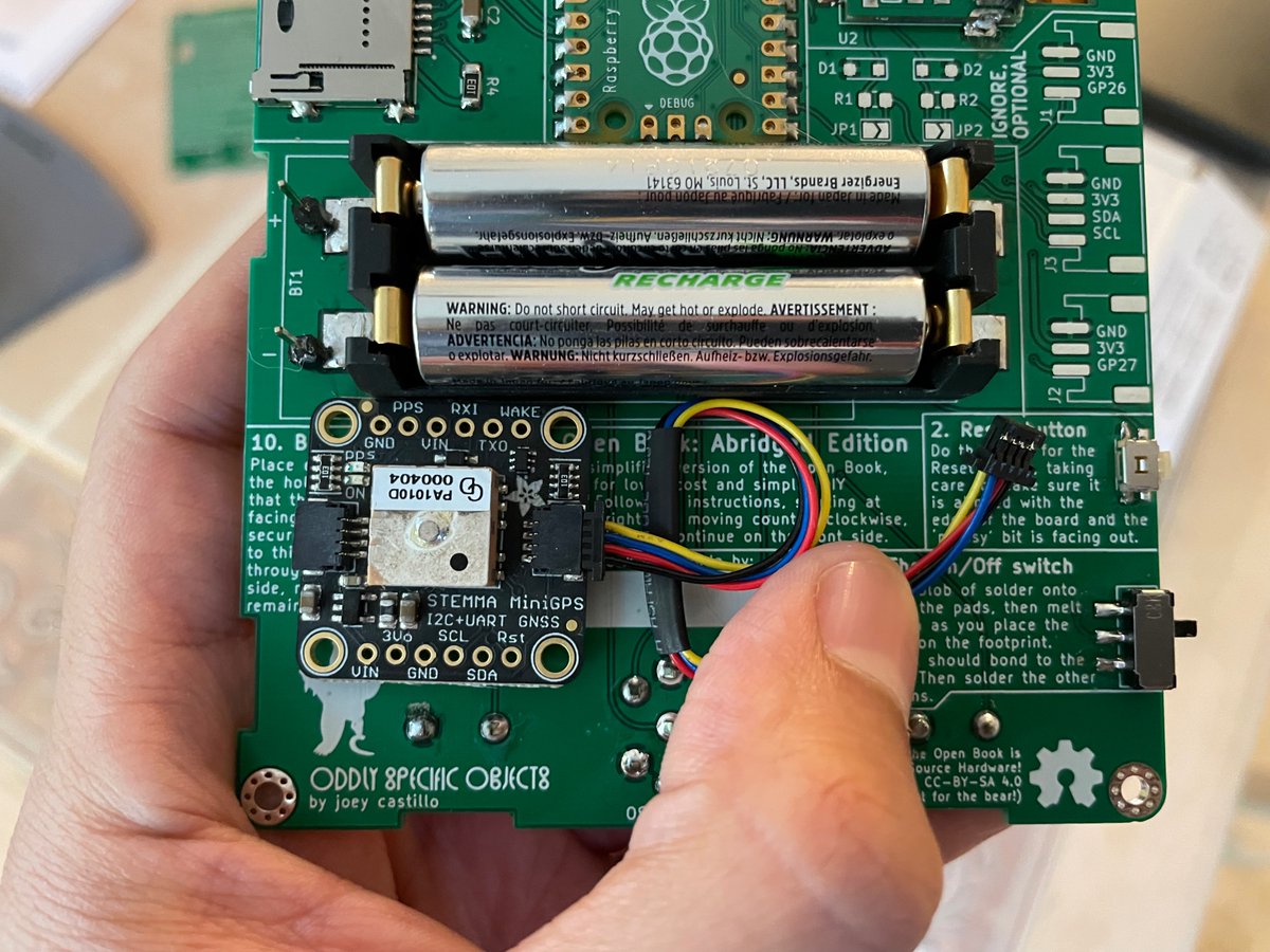
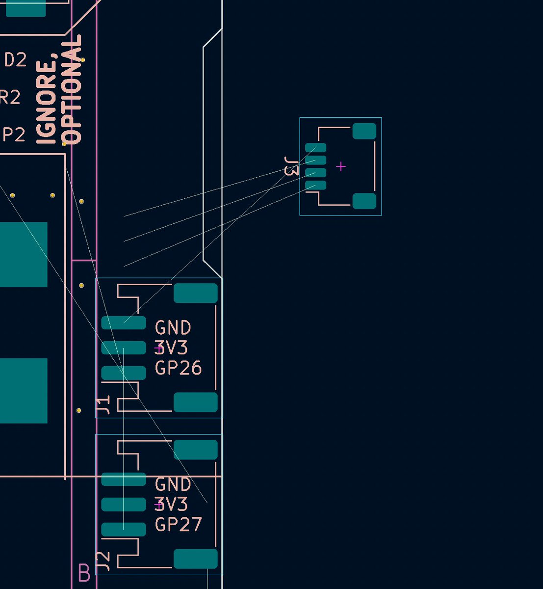
castellated module needs a lil scoot. and we can remove the hole for the flex cable that we don’t need anymore.
(original)
Replying to @josecastillo
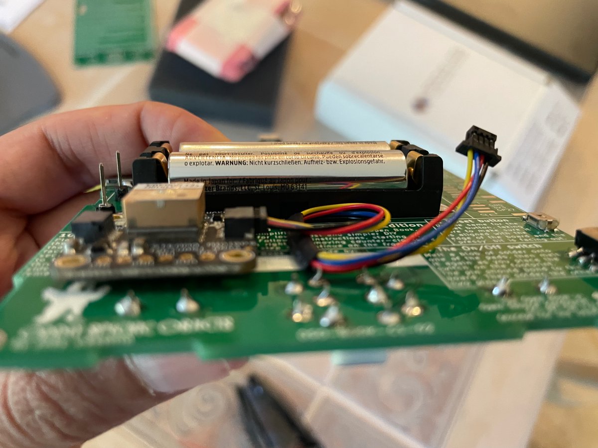
also instead of having it face out toward the world? Let’s have it face in toward the inside of the case. The case is going to have to be at least somewhat thick to accomodate the AAA batteries; that leaves tons of room for extra stuff like this GPS inside the device.
(original)
Replying to @josecastillo
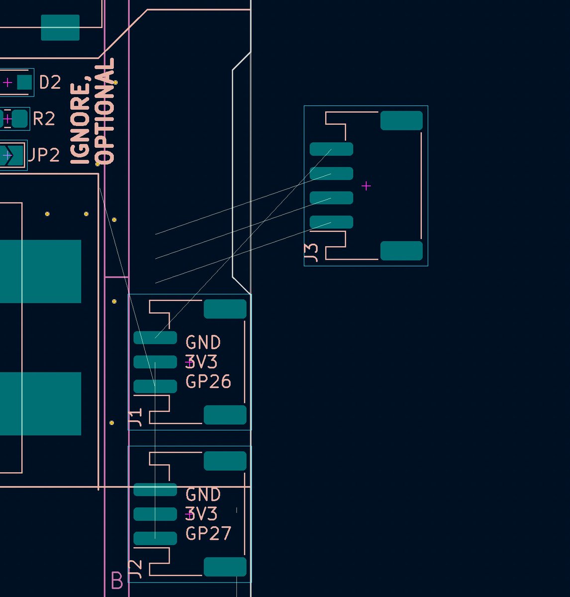
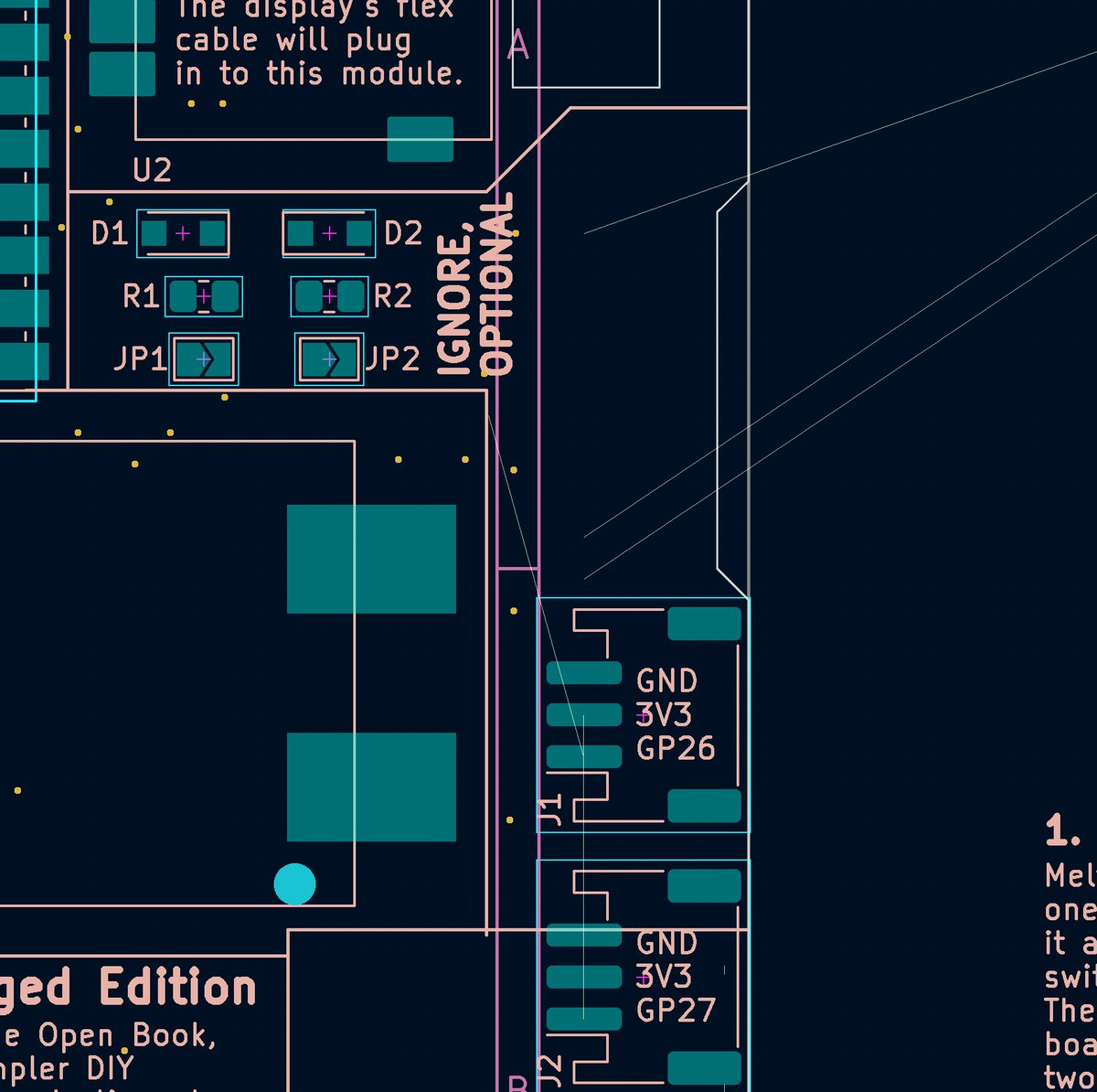
this leaves the question of what to do with that third JST-PH connector. Answer: turn it into a JST-SH connector! Times have changed since I first did this, Adafruit seems to be standardizing on STEMMA QT for I²C stuff, so why not skate to where the puck already went.
(original)
Replying to @josecastillo
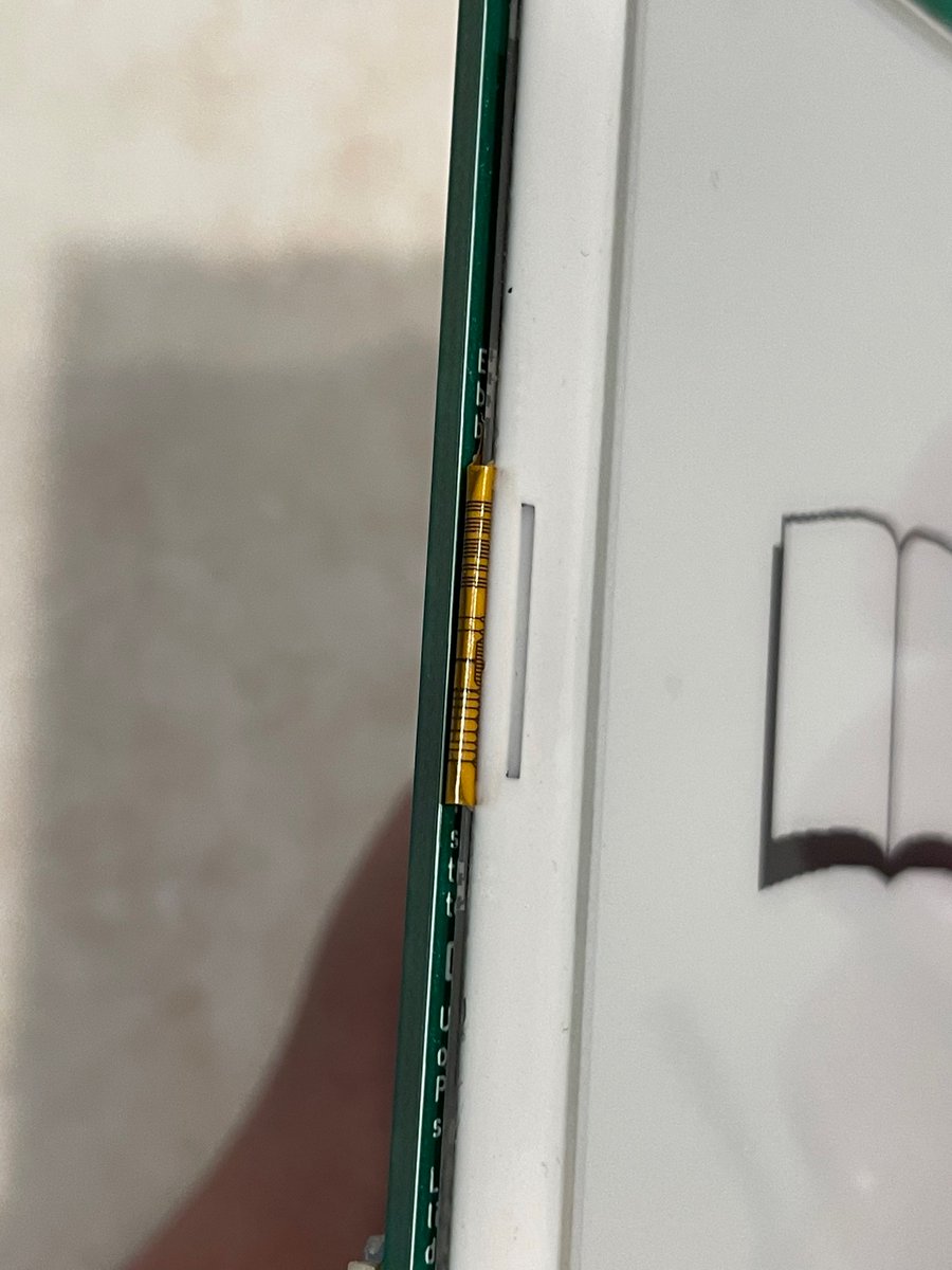
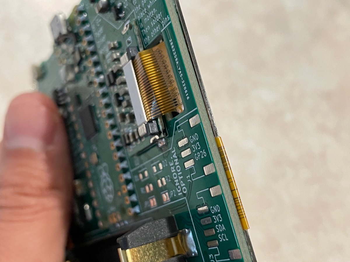
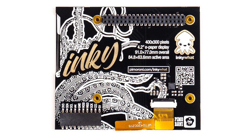
I’ve never liked this method of squishing the cable below the screen and routing it through a hole, but for a long time I didn’t have any better ideas. Using a notch will make it way easier to route since it just has to fold over and go into the slot (like the @pimoroni inkywHAT)
(original)
Replying to @josecastillo
this one feels big: since the beginning of the beginning, I’ve had three JST-PH ports along the left side of the device. but at the suggestion of @dcelectr, I’m rearranging them in order to add a notch to route the flex cable for the e-paper display…

(original)
Replying to @FrederikBanning
Electrically yes; mechanically no. Good Display sells a 5.83" and a 7" display that use the same connector and I have tested them, so if you wanted to do a bigger PCB you could. But the refresh is slower and the partial refresh story is unclear; may not be a good user experience.
(original)
Replying to @josecastillo
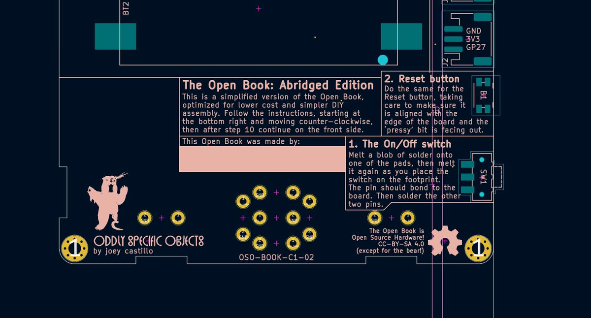
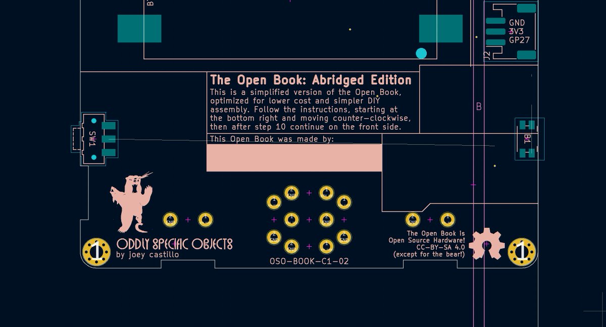
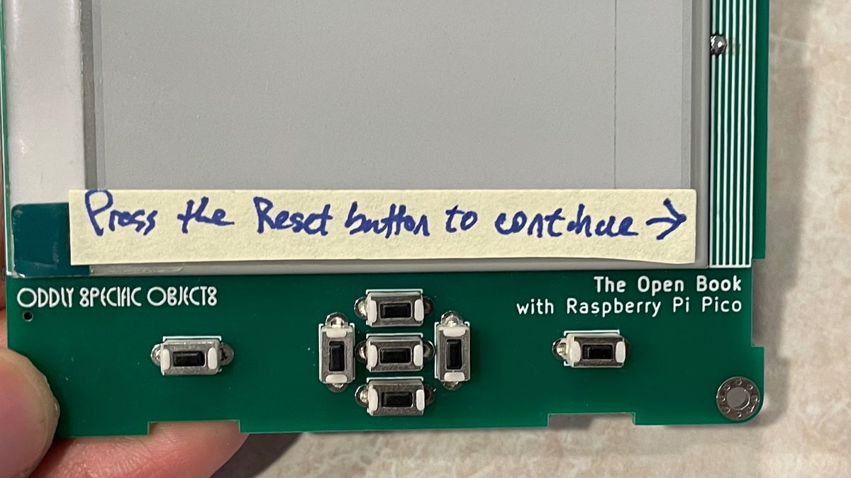
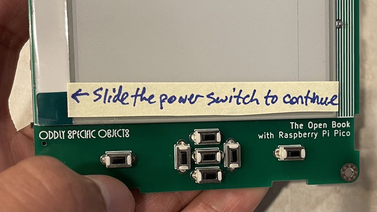
this next one is surprisingly important from a UI/UX perspective: the reset button and power switch need to be aligned to the bottom of the e-paper display, so I can do this:
(original)
Replying to @josecastillo
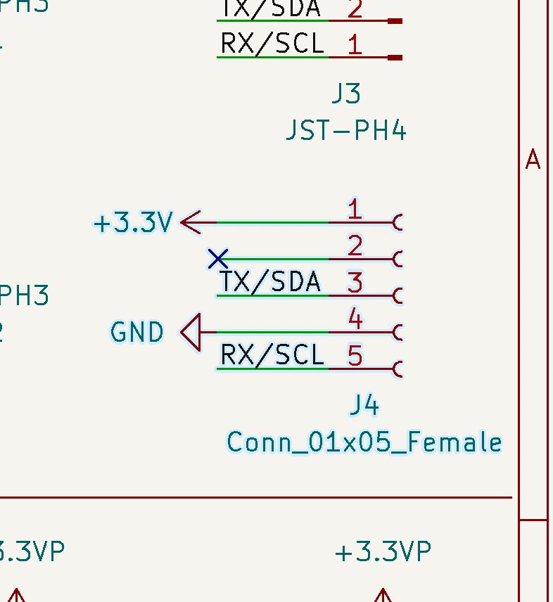
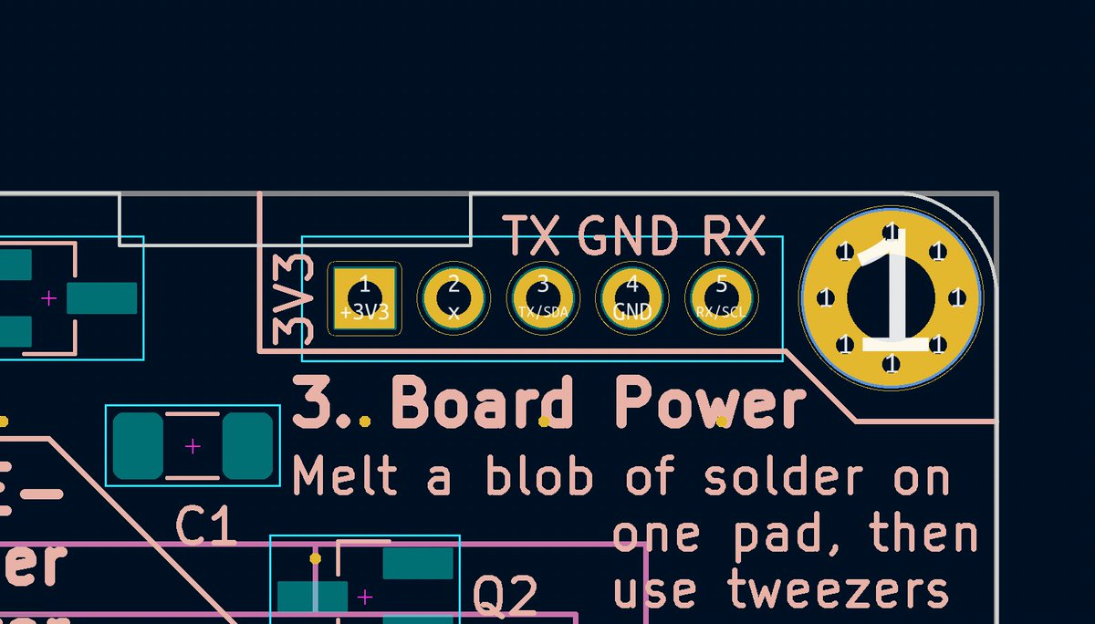
next, removing these pins that I never used. I’ll have a way to get to them via a JST connector, but removing the 3V3 power on a through hole means no more exposed power pins on the front of the device, which I like.

(original)
Replying to @RonKJeffries
working on it
(original)
Replying to @josecastillo
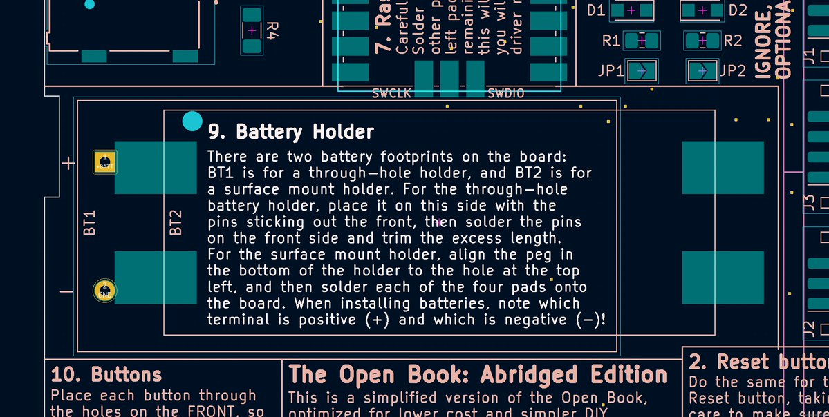
first up: committing to the surface mount battery holder. I had put footprints for both on at first, but the SMT one is slimmer and nicer. also moved the mounting pin: it was on the wrong corner, which had made the battery polarity illustration exactly wrong.
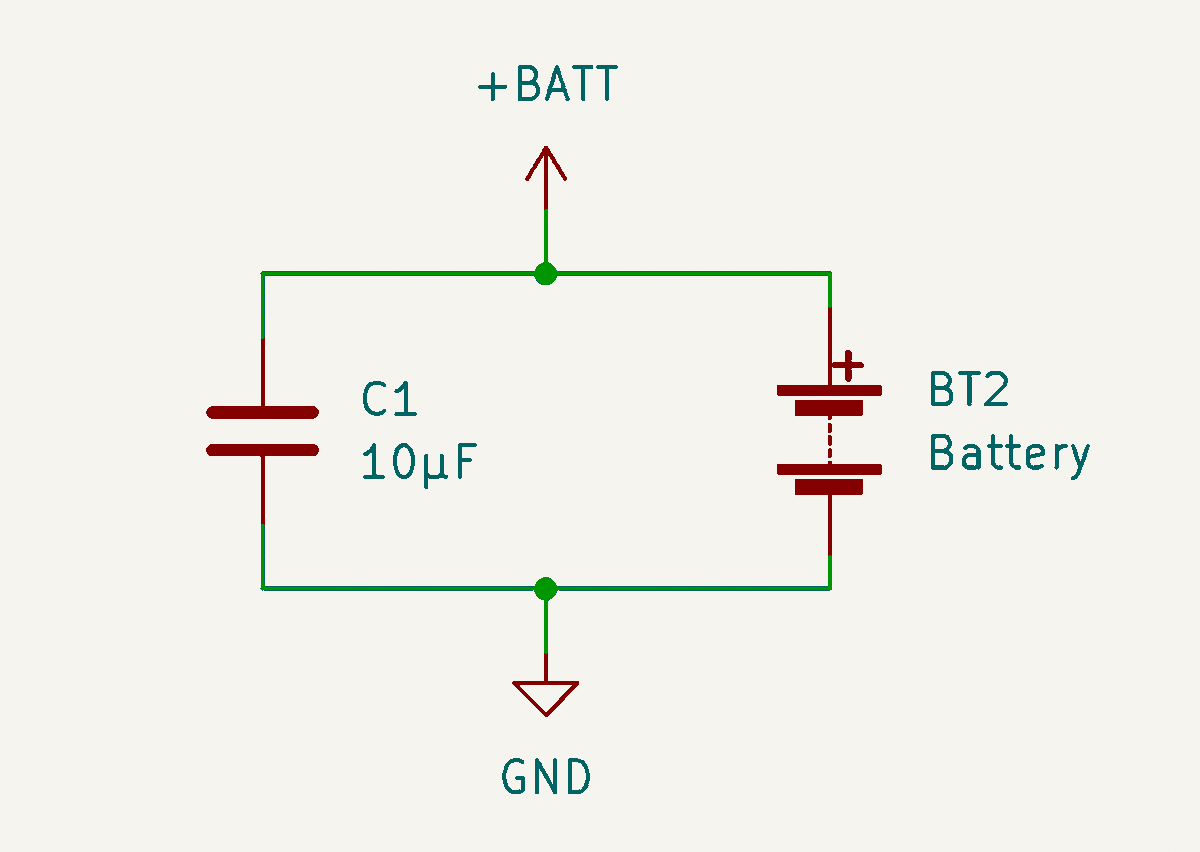
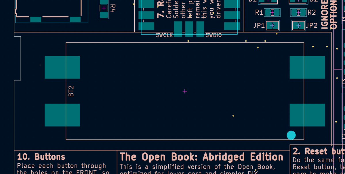
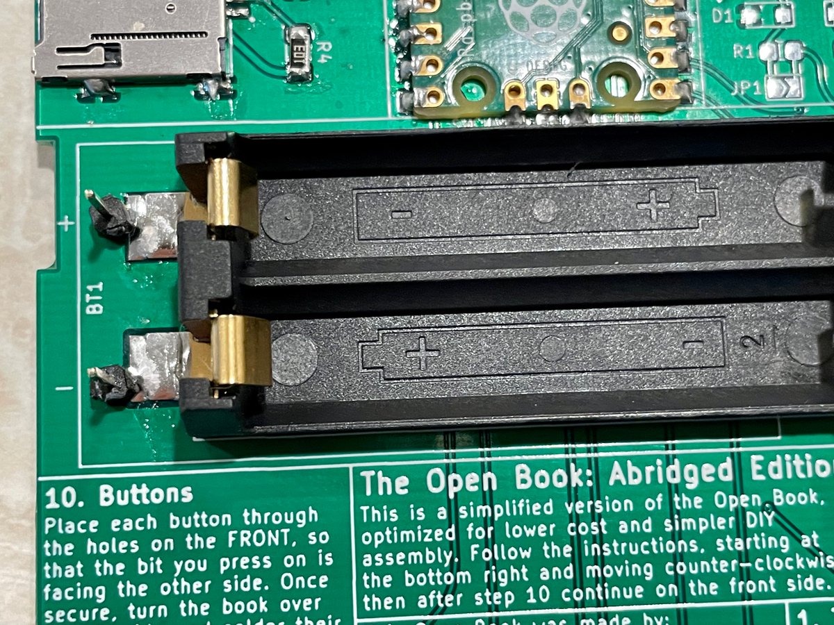
(original)
okay. this morning exercise: what I hope will be the last revision of the pi pico book. Some more changes than I had planned, but all mechanical; nothing electrical. gonna share as I go.
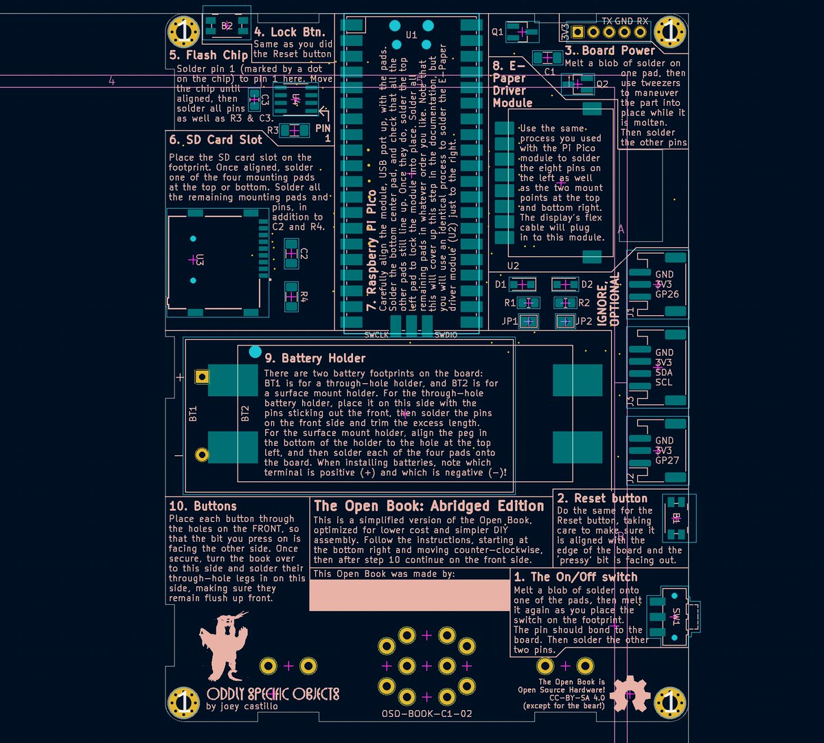
(original)
Replying to @marinusklasen
The gist of the story is simplify, simplify, simplify. Right now the Pi Pico book is my attempt to get some kind of legitimately DIY’able hardware in folks’ hands ASAP. Alas it sacrifices stuff like wireless in favor of being as easy as possible to build. Still: watch this space.
(original)
Replying to @VE7FIM
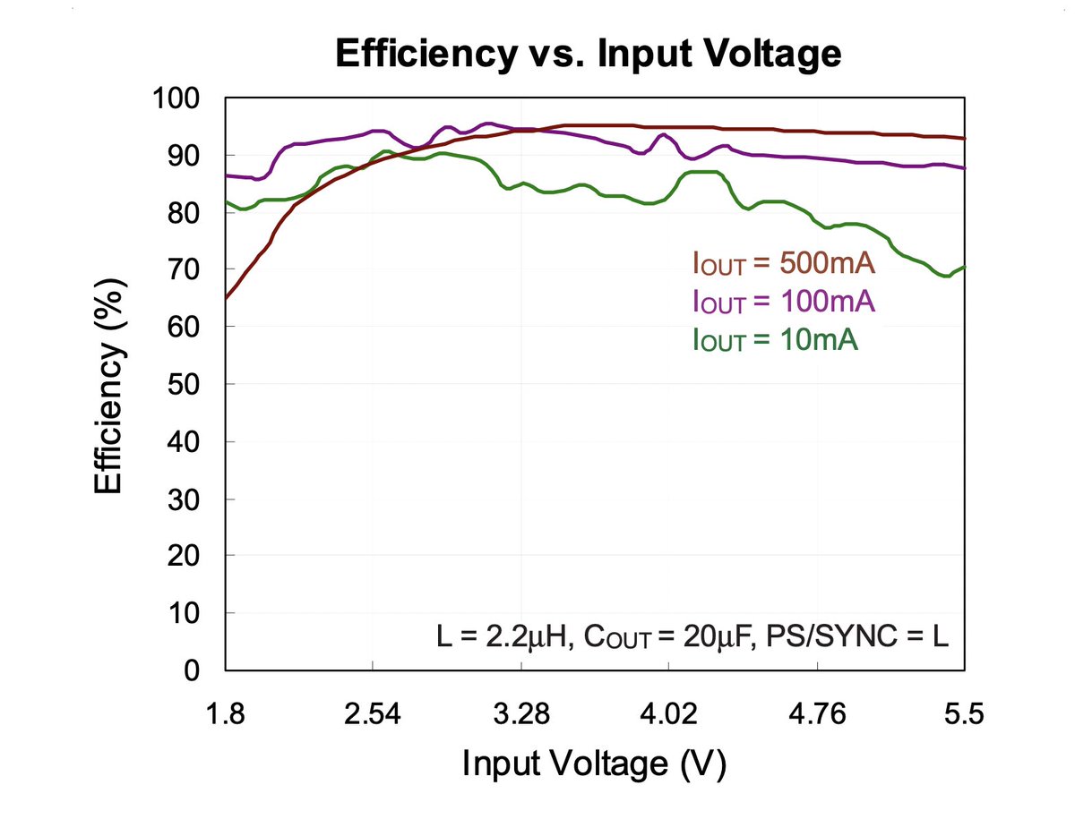
Interesting! Yea my situation is powering VSYS directly via a PMOS, and at low current draw the regulator seems to have a sweet spot for efficiency just below 3.3 volts. https://www.richtek.com/assets/product_file/RT6150A=RT6150B/DS6150AB-05.pdf
(original)
Replying to @VE7FIM
One question: what’s your supply voltage? I’m doing my testing at 2.4V, because that’s what I expect from two NiMH batteries in series… but if your VSYS is 5 volts, the power supply might not be as efficient there (my firmware pulls ~8 mA at 5V and ~9 mA at 4.2 V)
(original)
Replying to @MattHartman
Fun fact: before I partnered with Crowd Supply to launch the watch, I had been brainstorming with folks at The Prepared’s workshop about using a Vickrey auction to try to facilitate price discovery. I’m still uncertain whether I priced it correctly, but then, I’m still learning.
(original)
Replying to @Mobile_Dom
Unclear. I have one on hand here to play with, but TBH wifi isn’t on my radar screen for the Pi Pico book. I think it represents feature creep for phase one, and I’d rather target wifi with a future ESP32 version, which supports better antenna placement and lower power operation.
(original)
Replying to @bjornsen_
Nordic nRF-PPK2 Power Profiler Kit II, and the nRF connect software! Great piece of kit if you can get it. https://www.adafruit.com/product/5048
(original)
Replying to @josecastillo
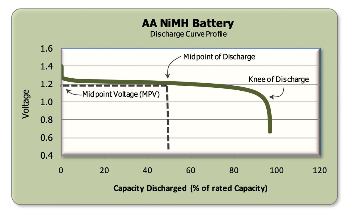
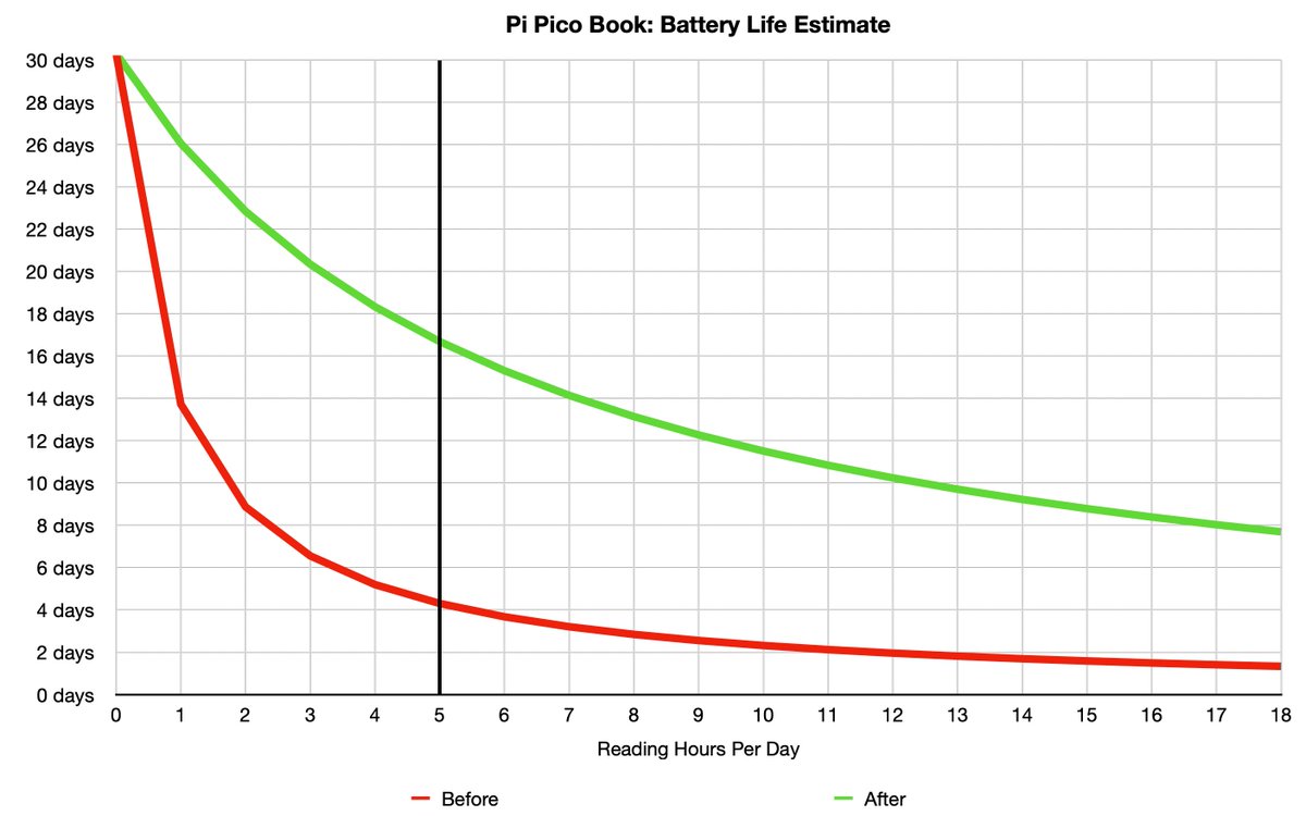
(in practice I don’t think we’ll get all 800 of those mAh; once we reach 80-90% depletion, I think we’ll have to force the device into dormant mode to avoid over-discharging the batteries. but still! an improvement to be sure.)
(original)
Replying to @josecastillo
Rough guesstimate to be sure, but: assume 800 mAh capacity in a rechargeable AAA cell, and typical usage to be five hours of active reading per day. This little morning exercise moved us from 4-day battery life to over two weeks of typical use.
(original)
Replying to @josecastillo
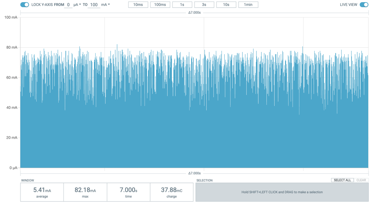
Best: detect if VBUS is present; if not, there’s no USB cable plugged in, and therefore no need to run the USB clocks. Down from 28 mA to under 5.5 mA. That’s an 80% reduction in wake mode power consumption! Five times the battery life for reading books.
(original)
Replying to @josecastillo
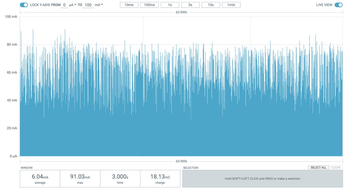
Even better: disabled all clocks in sleep, except for the ones responsible for USB connectivity. Down from 28 mA to just about 6 mA.
(original)
Replying to @josecastillo
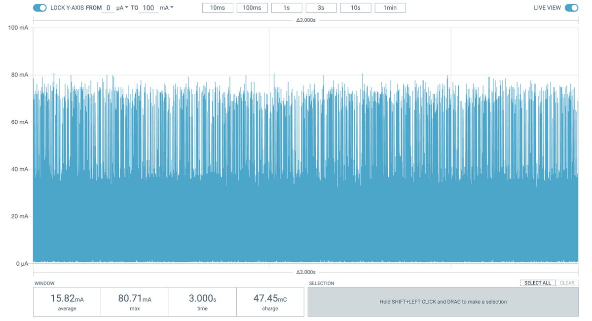
better: disabled the timer 0 interrupt; now down from 28 mA to under 15.
(original)
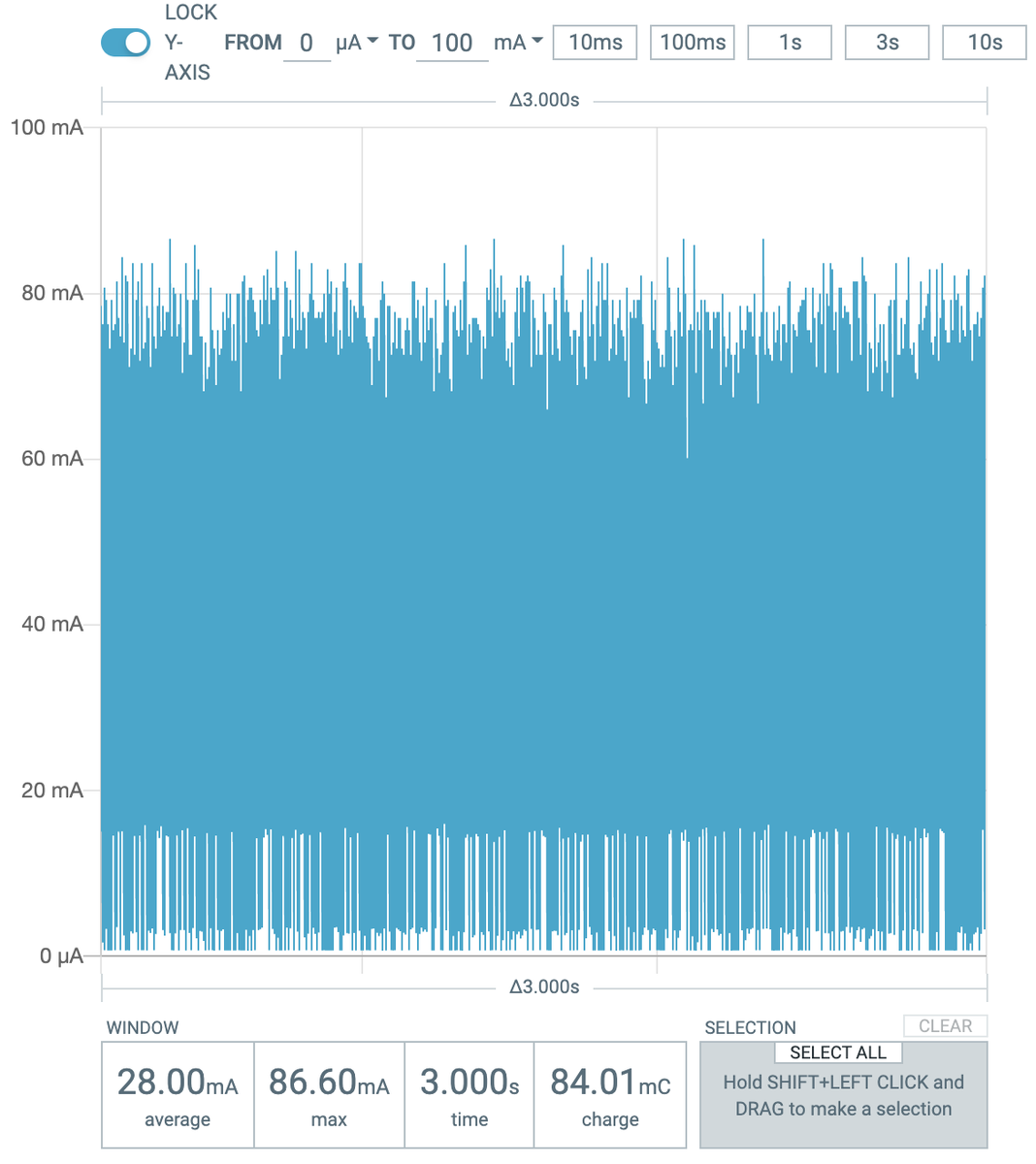
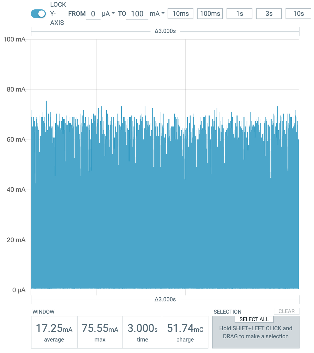
sweating the small stuff: implementing interrupt-driven button input in Focus for the Pi Pico book (before, the buttons were polled). No clock gating or anything so far; just picking a sleep mode and adding a __wfi(), and I’ve saved almost 11 mA with no change in user experience.
(original)
whenever I see someone wearing a Casio F-91W in the wild, I can’t help but strike up a conversation. People ADORE these little watches; it’s a surprisingly high level of stoke for such a simple object.
(original)
Talking about battery life in today’s Teardown Session, a question came up: what was the firmware change that so significantly reduced Sensor Watch power consumption? I couldn’t find the thread live, but it’s worth sharing. I think this was my finest work: https://twitter.com/josecastillo/status/1491897251148533769
(original)
Happening right now: Sensor Watch Teardown Session! In which we talk manufacturing, testing and shipping, do some stargazing and maybe even talk about some other Oddly Specific Objects. Live at the link: https://www.youtube.com/watch?v=lqHFx0ze8OQ
(original)
Sensor Watch is now my essential watch for everyday wear. This morning I’m using the World Clock face to see the local time in Portland: relevant because at noon Pacific (<4 hours!) I’ll be live-streaming a Teardown Session w/ @helenleigh of @crowd_supply! https://youtu.be/lqHFx0ze8OQ

(original)
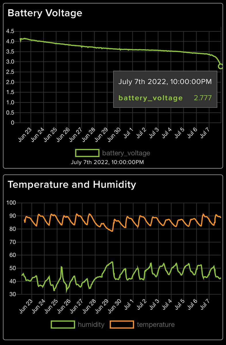
Last night the LCD FeatherWing battery test concluded! Just shy of 16 days on a compact 400 mAh battery, with an always-on display and telemetry uploaded every 15 minutes. I’ll be honest: I was hoping for more, but still. That’s not bad!
(original)
RT @molecularist: Soldered up @josecastillo’s LCD Wing, changed pin headers to socket headers on my @unexpectedmaker FeatherS2, modified ex…
(original)
Replying to @theavalkyrie
this is so great I keep wanting to retweet this again.
(original)
Replying to @josecastillo
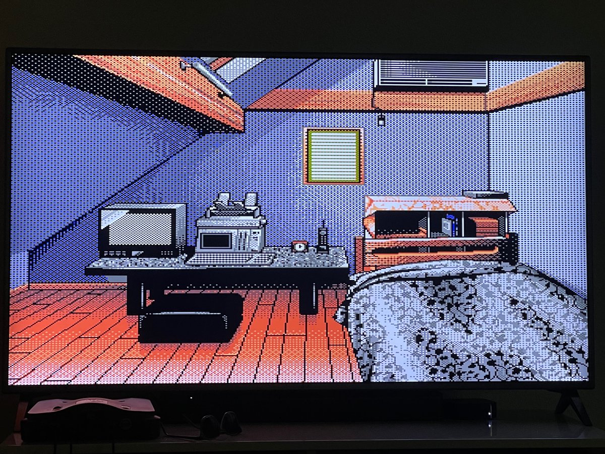
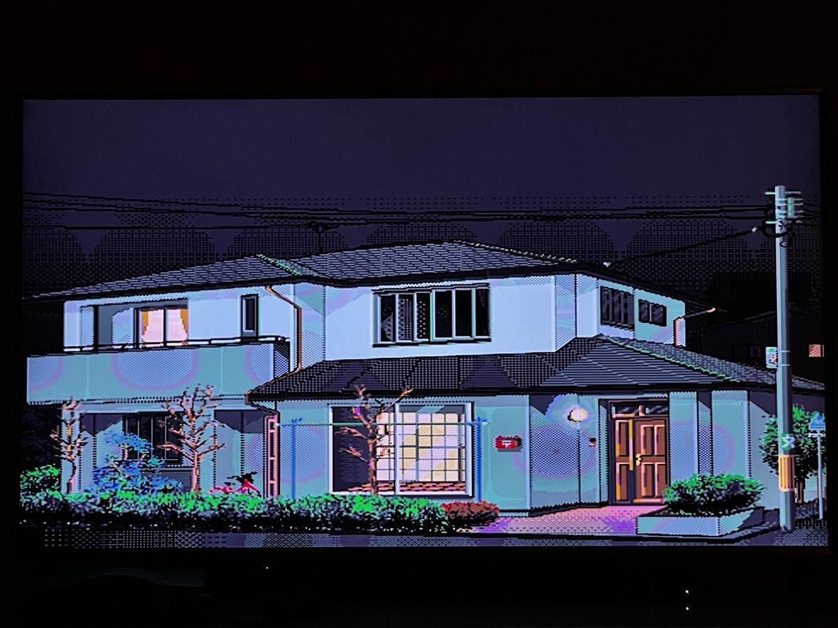
I think I played this game in QBASIC.

(original)
wow do vaporwave channels on youtube have a vibe


(original)
Replying to @gennyble
I only ever think of you as Genny FWIW.
(original)
RT @theavalkyrie: 👀

(original)
Replying to @EconomicsBread
Defining the line widths for the ruler at the left. Not exactly FizzBuzz, but close!
3 * (i % 5 ? 1 : (i % 10 ? 2 : 3))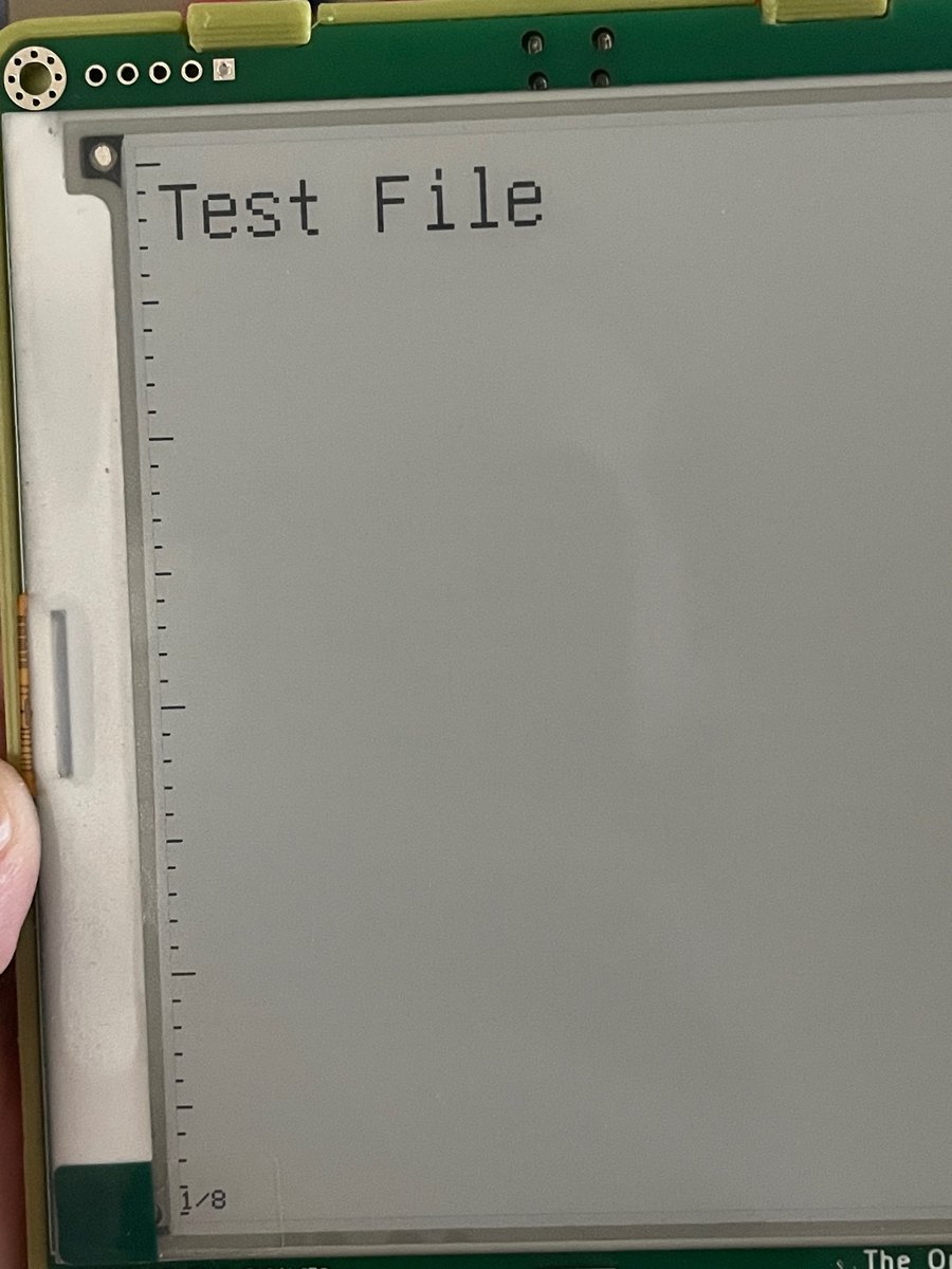
(original)
oh my goodness, I just actually had to implement FizzBuzz. like, for legitimate reasons, I needed to do this in my code.
(original)
RT @crowd_supply: On tomorrow’s livestream @josecastillo will be talking about the final stages of the Sensor Watch campaign, as well as so…
(original)
Two Sensor Watch updates today:
- we’re streaming a Crowd Supply Teardown Session LIVE tomorrow at noon pacific!
- New backer update is live! In which I share some notes about working with @PCBWayOfficial and @MakeAugusta to build the first 412 boards. https://www.crowdsupply.com/oddly-specific-objects/sensor-watch/updates/green-boards-underway-battery-experiments-and-a-teardown-session-tomorrow
(original)