Tweets
Replying to @josecastillo
Tag yourself, I’m U+FFFD REPLACEMENT CHARACTER �

(original)
Replying to @josecastillo
my pagination code is still broken. but before, it was even more broken. so this is an improvement.
(original)
Replying to @josecastillo
discovered a hilarious footgun when moving my pagination code back to the device: on the Pi Pico, printf statements log to the UART on pin 0, which is also the pin I’m using to gate power to my peripherals. A simple printf(“foo”) is enough to power down my SD card and display. 🤦🏽♂️
(original)
morning project: I got tired of trying to figure out text wrapping + pagination on-device, so I ported the Open Book’s typesetter to macOS for some proper printf debugging. This is the last task remaining for libros, the Open Book firmware, to function as a useful e-book reader.

(original)
This is the way. https://twitter.com/whoismarkspicer/status/1545050564337082368
(original)
Replying to @GeekMomProjects, @bradanlane and @WellsFargo
My dad lied *once* about his birthday in the 1960s to get a summer job, and it took decades to figure out. I was a teenager by the time they got the paperwork sorted.
(original)
Replying to @mLedwon
This one was so obvious, like, you can be both selfish and altruistic, just pull the lever! I think 41% of people misunderstood the question.
(original)
Fun experiment: I loaded the new Sensor Watch board and a very low battery into the gold-tone watch, just to play with current consumption toward end of life. Watch the voltage drop when illuminating both LEDs, then gradually climb back up as the battery gets used to 10 µA again.
(original)
Replying to @josecastillo
Rich man go splat. It’s like 20% “that’s blood money!” and 80% “fuck that guy.”
(original)
I’m glad to see we’re mostly on the same page. https://neal.fun/absurd-trolley-problems/

(original)
Replying to @bwshockley
The new more efficient one; I made these optimizations in February, so they were tested and merged in well before I shipped them in April.
(original)
Replying to @tablatronix
the more I think about it, I think I might just have a thing for brutalism in design. It is what it does.
(original)
Replying to @josecastillo
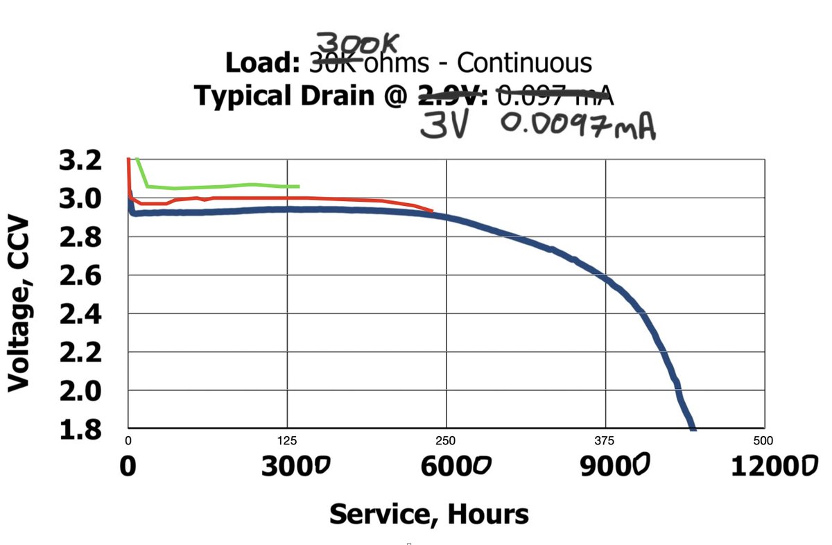
The state of play: blue line is from the data sheet (using an order of magnitude more power, so ignore my scrawling on the scale: it dies at 1000 hours). Red is the old firmware, nearing hour 6000, curving downward earlier than I’d like. Green is the new firmware, sitting pretty.
(original)
Replying to @josecastillo
Meanwhile, new battery test is at day 135 and 3.06 volts. This is a fantastic number IMO; it’s hard to overstate the impact of that one big day of microampere hunting.


(original)
Replying to @josecastillo
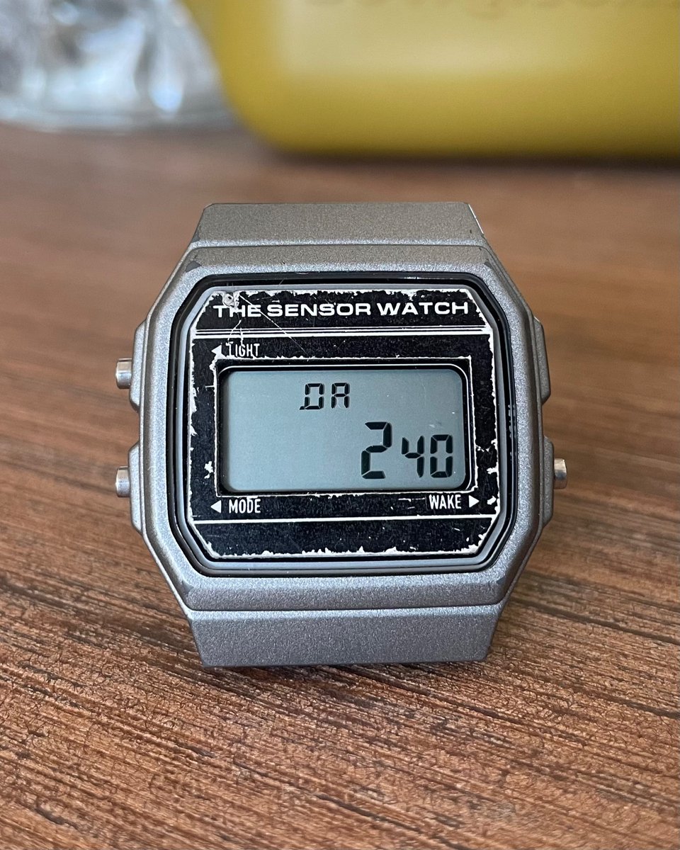
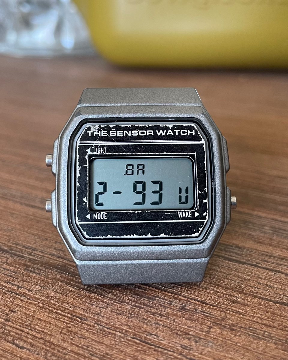
Battery test, day 240: 2.93 volts. Eight months into the test, we are definitely making the turn. Again, this is with the old, less efficient firmware, so it’s more of a floor than a ceiling. At this point I think the odds are better than even that it makes it a year, but barely.
(original)
Replying to @a2
I bought it in the heat of the moment.
(original)
RT @lixielabs: Thanks @josecastillo for the tip to print PCB dummies in two thin halves (glued together) to preserve detail on both sides!…
(original)
Replying to @dcelectr
I’m sure my parents are relieved that I didn’t know this as a child.
(original)
Replying to @josecastillo
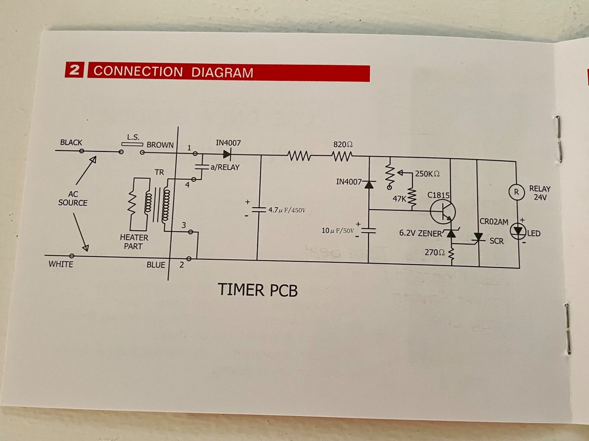
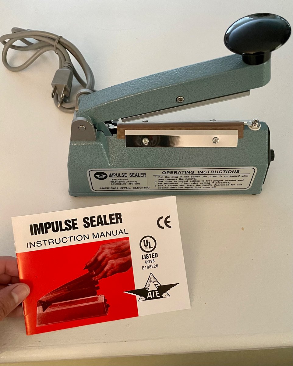
it also includes a schematic diagram inside! like, when’s the last time you bought an object that did that?
(original)
I just unwrapped this brand new heat sealer from McMaster and wow is it tapping into an aesthetic.


(original)
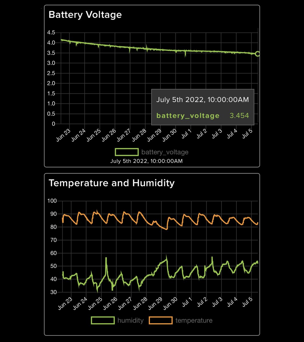
We’re very nearly two weeks into the LCD FeatherWing battery test, and I think we might be making the turn. Battery voltage down to 3.45 volts, and the curve seems to be changing slope downward. https://io.adafruit.com/joeycastillo/dashboards/lcd-featherwing-battery-test

(original)
Replying to @AlperenAkkuncu, @ReimuNotMoe, @Unica_Research, @sad_electronics, @GregDavill and @robin7331
When I had my workstation in NYC, I used an old Dell UltraSharp U2713HM that I got like eight years ago, plugged into my MacBook Pro. TBH though I feel just as effective with the built-in display on my M1 MacBook Air, as long as I have a mouse for zooming in and out a lot.
(original)
Replying to @KeanM and @fullmoon6661
I’m tempted to rely on it (with the correct diode) just because A, it has worked on so many devices for so long, B, this circuit is only relevant while flashing code or testing via USB, and C, it’s hard to even get it to be an issue, what with flashing both LEDs at full power.
(original)
Replying to @KeanM and @fullmoon6661
that does explain it, full stop: there is no output capacitor. There’s 10µF on the other side of the diode, but I was so concerned with stabilizing the 3.0V rail that I neglected a cap on the regulator output. Makes total sense now that a big change in current draw could do this.
(original)
Replying to @josecastillo
The final test also does device programming: I double tap the reset button, which both tests the button and puts the board in bootloader mode. Finally, I copy the Movement firmware from my computer to the board, which both tests the USB port, and programs the watch to be a watch.

(original)
Replying to @josecastillo
Oh right! Closing out the testing thread. I mentioned earlier that green was the penultimate test. Closing out that test involves plugging in this special sensor board, which confirms that all the pins on the 9-pin connector are connected, and that none are bridged…
(original)
Replying to @josecastillo
now I can move on to my other major task for the weekend: paperwork. Paperwork that will lead to a very cool outcome. but paperwork nonetheless.
(original)
Replying to @fullmoon6661
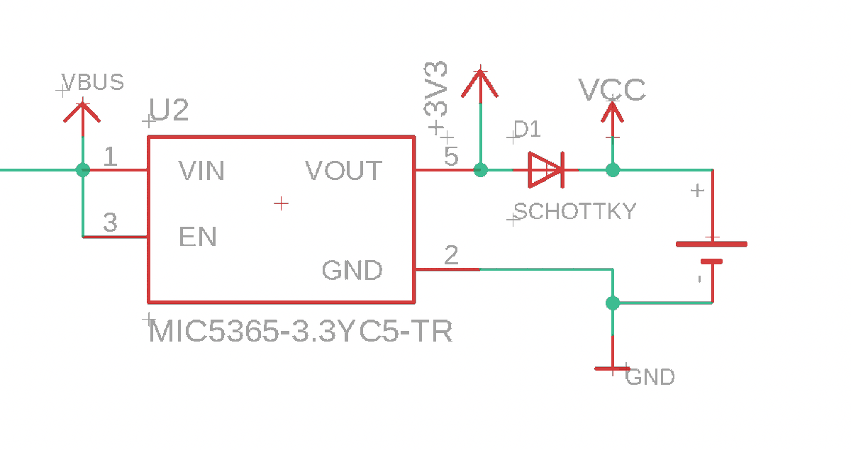
It’s on the regulator output, to prevent any positive voltage at VOUT when a coin cell is connected directly to VCC. (there’s no diode between battery + and VCC because when a battery is installed, the USB port becomes mechanically inaccessible, so there’s no way to backpower it)
(original)
Replying to @mattk
It seems it was an issue with the Schottky diode that I swapped in during supply chain troubles. Doubtless some subtlety that I overlooked when comparing specs, but swapping back fixes the issue. It seems I will be able to get my old diode again, so that is going to be my fix.
(original)
Replying to @josecastillo
OH MY GOD. it’s the diode. I can’t imagine what about the new one is is so different that it would create an issue, but there’s no doubt: swapping in my old part restores the old behavior. I could puzzle on this some more, but my old diode is back in stock at a MOQ of 3000. Sold.

(original)
Replying to @josecastillo
The only thing that changed in that circuit is that I swapped a Schottky diode for another similar Schottky diode since my old one was out of stock. The regulator is the same. Even the PCB is the same. I suppose the next stop is to swap in my old diode and see what happens.
(original)
Replying to @josecastillo
UGH. Same power trace, but powered directly from 3V, as we would be from the battery. No spiky peaks, RTC ticking right, it looks exactly the way I’d expect. Whatever funkiness is happening, it has to be to do with the regulator and the diode. This is infuriating, I have no idea.
(original)
Replying to @josecastillo
(that’s not PWM, I’m just alternating setting the red and green pins high every half second, or I guess longer when the funkiness takes hold)
(original)
Replying to @josecastillo
Well, it’s not R5. Tested this change on a few boards and the issue is still present. Also did a power trace: no doubt about it, something funky is happening when the red LED is on. Increased current draw beyond what I’d expect, noisy peaks. I think a bigger resistor is my solve.
(original)
Replying to @josecastillo
This issue will affect folks who:
* have an app that uses the RTC
* that lights up the LEDs at max brightness
* and are testing while tethered to USB.
I need to fix it, but I’m fixing it for these folks (of which, to be fair, I am one. so I really do want to get it right.)(original)
Replying to @josecastillo
also worth noting: this issue is all just me being intensely thorough. It won’t affect anyone getting their watch and flashing code onto it, and once it’s on your wrist the 3.3V regulator is essentially dead weight; it isn’t powered and can’t affect anything.
(original)
Replying to @josecastillo
either way, the impetus for this whole pin was laziness on my part: I sense there’s probably a way to detect in software if a USB host is connected, and power down the peripheral otherwise. If removing R5 does indeed fix this issue, I can mark R5 DNP and write some code instead.
(original)
Replying to @josecastillo
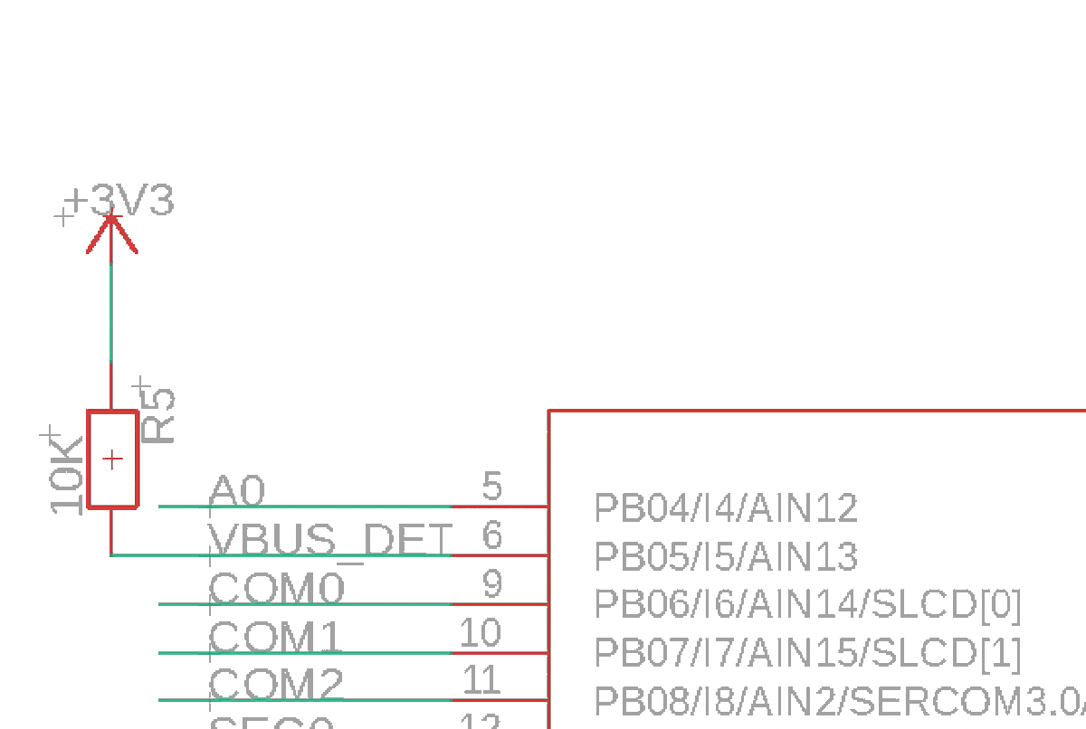
another clue: removing R5 seems to pretty reliably get it ticking again. R5 connects the 3.3V output from the regulator to an input on the MCU (which runs at 3.0 volts). The pins should tolerate up to 0.6V over VCC, but maybe the sudden LED current draw is causing spikes?
(original)
Replying to @josecastillo
on the plus side, this means I’m solving a problem that’s not the 90% use case. This issue doesn’t affect the watch while worn, which is good news. The bad news is you do need to plug it in to USB to program it, which means I need to figure out what’s going on.
(original)
Replying to @josecastillo
Oh no. the plot thickens. On further testing, this issue only seems to manifest when powered from USB. If sourcing power from the battery or the testing board, there’s no issue. Which makes me suspect that the current draw of the red LED is a symptom of a bigger problem.
(original)
Replying to @josecastillo
This week I plan to order a reel of 680 ohm resistors and ship them to @MakeAugusta so that they can resume manufacturing of the boards. Mega thanks to them for being willing to ship me one panel to test first; it would have been a mess to rework all 400 of these after the fact!
(original)
Replying to @josecastillo
…but the fact is, in the year since I was first tweaking resistor values, I’ve written much better support for color blending in the firmware. You can still get that rich, satisfying yellow; you just have to dim the green LED a bit. Which, hey! Longer battery life. Still a win.
(original)
Replying to @josecastillo
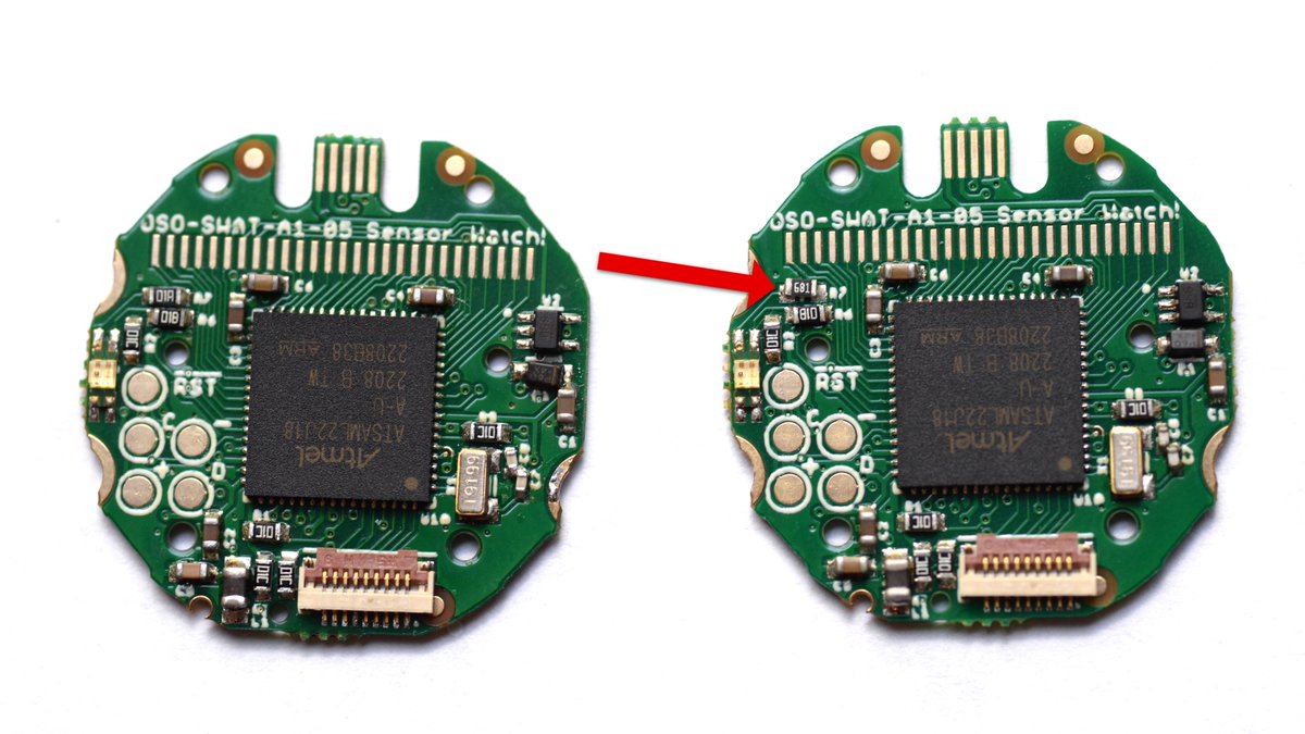
RESOLUTION: I swapped out the 100Ω resistor on the red LED for a 680Ω. This keeps the current draw on the red pin below the SAM L22’s recommended max, and it fixes the RTC issue I was seeing! It does mean that the red LED is not as bright, and the default yellow’s a bit greener…
(original)
Replying to @fast_code_r_us
Yep! I got mine from Adafruit: https://www.adafruit.com/product/4774
(original)
Replying to @josecastillo
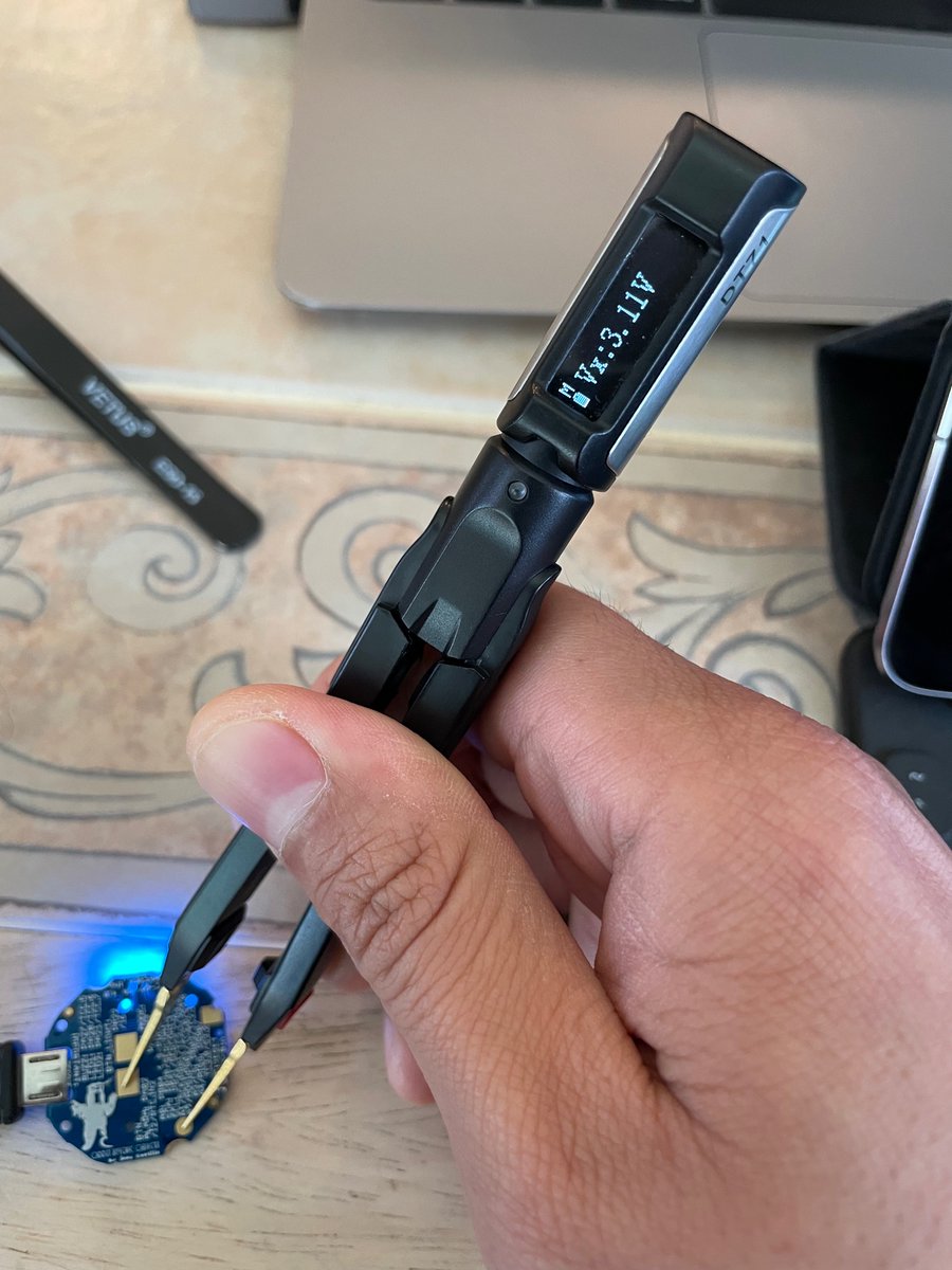
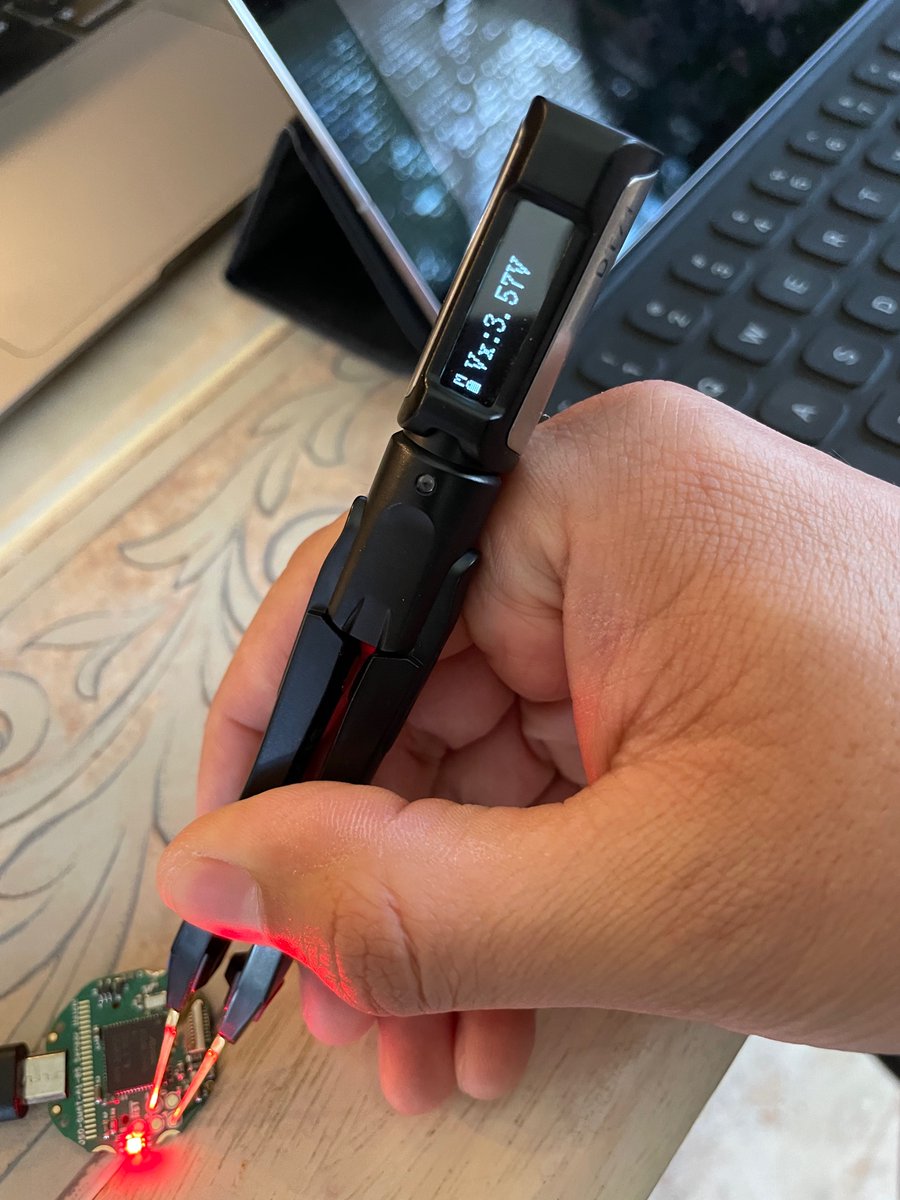
Fast forward to today, I’m using a new batch of chips, and it seems that whatever I’ve done is causing Bad Things to happen. I don’t even know how, but my 3V rail is reading nearly 3.6V when stuck on red — close to the absolute maximum for our microcontroller.
(original)
Replying to @josecastillo
In the end I discovered that 100Ω gave me a deep, rich, satisfying yellow. It did mean that the red LED pin would in theory draw more current than the SAM L22 datasheet allows. But in practice it seemed to work fine, so I figured maybe the MCU had some protection, and I moved on.
(original)
Replying to @josecastillo
It reminded me of something I did way back in the beginning, when I was tuning resistor values to blend shades of red and green. The green LED is super bright at 1KΩ — great! Alas, red was too dim at 1KΩ. So I spent some time testing different values… https://mobile.twitter.com/josecastillo/status/1386390291335159810
(original)
Replying to @josecastillo
In the end though, I tracked down one thing I could do that would make the RTC tick: when I disabled the LED, I got my expected 2 Hz callback. Basically, if I used it to blink red and green, it wouldn’t work. but if I did light up the LED, the RTC would hang. This was a big clue.
(original)
Replying to @bradanlane and @arturo182
Just the basic SAM D21, no external Flash chip or anything. It has room for the progamming firmware, as well as the watch bootloader and two test programs.
(original)
Replying to @josecastillo
This seemed to signal that the RTC wasn’t ticking, which I confirmed. I feared I’d mixed up a part, bought the wrong crystal or value of load capacitor. There was a lot of existential dread last night: I thought I HAVE to figure out what’s wrong, because this thing needs to ship!
(original)