Tweets
Replying to @moxnr
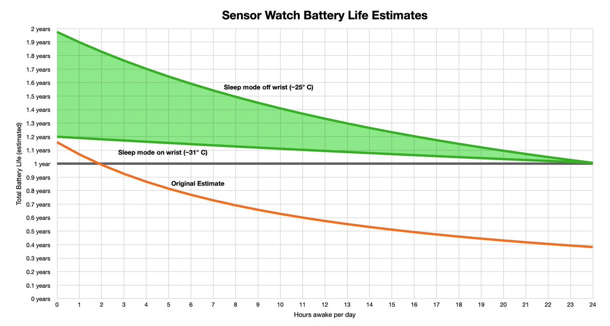
It’s funny: the difference in current consumption in sleep vs wake is so very subtle. Maybe 4 to 7 microamperes? But according to my estimates — and this is all in theory until the test watches run down — it’s the difference between one year of battery life and nearly two.
(original)
Funny thing: I’ve been calculating Sensor Watch battery life based on 2 hours awake per day. But the last few days I haven’t needed to wake it. Like it’s nice to have this highly versatile device on my wrist. But 9 times out of 10 I’m just checking the time, and it’s right there.

(original)
Replying to @anne_engineer, @oshpark and @adafruit
agreed! First time I’ve soldered one down as a castellated module; I love that it just lives on this board now.
(original)
Replying to @ryanteck and @oshpark
Haha I haven’t written the final test suite for it, but I am totally going to do that!
(original)
Sensor Watch tester in @oshpark purple. This was a triumph.
(original)
“we went to bottomless brunch but it turns out there is no bottom.”
(original)
It’s wild to me that two subtly different requirements can be fulfilled by wiring two pins in the completely opposite way.
Know your body diode. https://twitter.com/GregDavill/status/1534718092458496000(original)
🤞🏽 https://twitter.com/SleeplessRe/status/1534571915347492864
(original)
Replying to @josecastillo
“Next.” “Back.” “Up.” “Down.” “Left.” “Right.” “Go.” You don’t need a huge vocabulary to control this device. And the way I architected Focus, I sense I could do it by adding a VoiceCommandTask that generates events from voice, just like the ButtonInputTask does from buttons now.
(original)
A reply today reminded me of the old Open Book voice command test. The state of TinyML has changed since then! The Pi Pico has two whole cores; imagine running a model on one that could recognize each button’s name and use it to navigate our Focus-based UI.https://twitter.com/josecastillo/status/1205549284403355648
(original)
Replying to @BobMahar
Interestingly one of the core tenets of this project has been extensibility; there are three ports on the side that can support a microphone for voice commands, alternative input devices, or even simple I²C devices like gesture sensors: https://twitter.com/josecastillo/status/1190093573103988736
(original)
Replying to @hackerb9
That’s totally a fair point; I guess the thing I’m thinking about is that the silkscreen design (what with component designators and pin markings) is to some extent aimed at having marks that aid in assembly. If I go with this it’ll just be taking that one (to ten) steps further.
(original)
Replying to @hackerb9
Previous page feels like such a rare action to take though; probably 95% of the time you’re reading a book, you’re advancing the page. It feels less ergonomic to have the 5% action occupy the same space near your thumb as the 95% action.
(original)
Replying to @josecastillo
(yes I deleted and reposted this; felt like it made sense to have both side by side instead of putting the new one in a follow-up)
(original)
Replying to @josecastillo
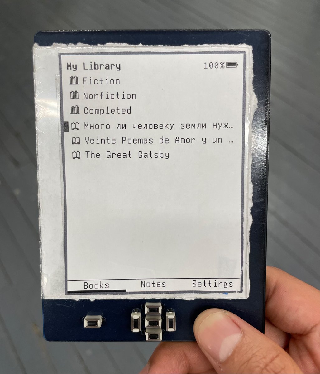
It looks weird to me, but I think that’s familiarity bias. It _feels_ much nicer, like I actually have more of a grip on it while my finger rests on the button. By comparison, holding the old device this way makes me feel like I’m pinching the corner and barely hanging on.

(original)
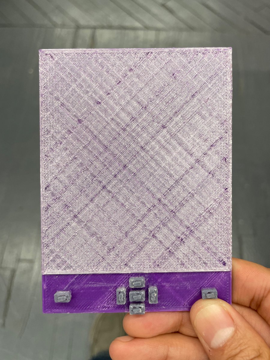
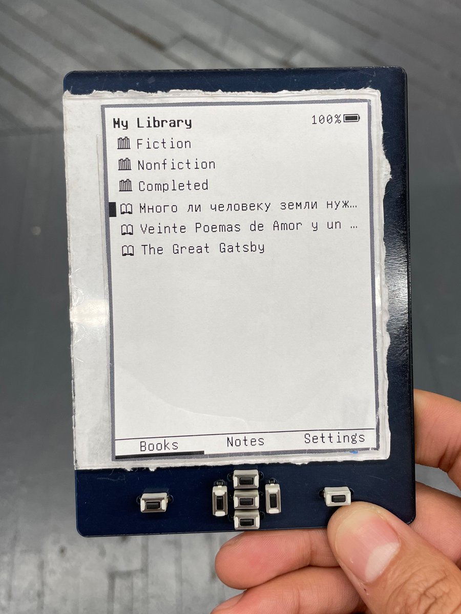
Today’s thought: killing sacred cows. Ever since the first plastic E-Book Wing mock-up (ca. 2019), the previous and next page buttons have been at the far left and far right. Today considering the possibility: is it more ergonomic to have them nearer to the center of the device?
(original)
Replying to @TheSethKerr
Totally fascinating! Once I saw this explanation it clicked for me — I just find it wild that I’ve been building this circuit unthinkingly for so long, yet my fundamental understanding of it was totally off base.
(original)
Replying to @josecastillo
I’m sure this is something I would have puzzled out after realizing my peripherals were still getting 2.7 V when switched off, but I’m thankful that Mathias pointed it out, and I’m stoked to now understand more about a circuit I’ve been building into gadgets for years. /thread
(original)
Replying to @josecastillo
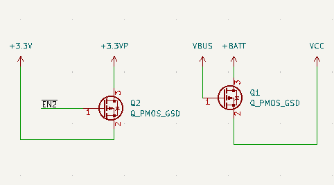
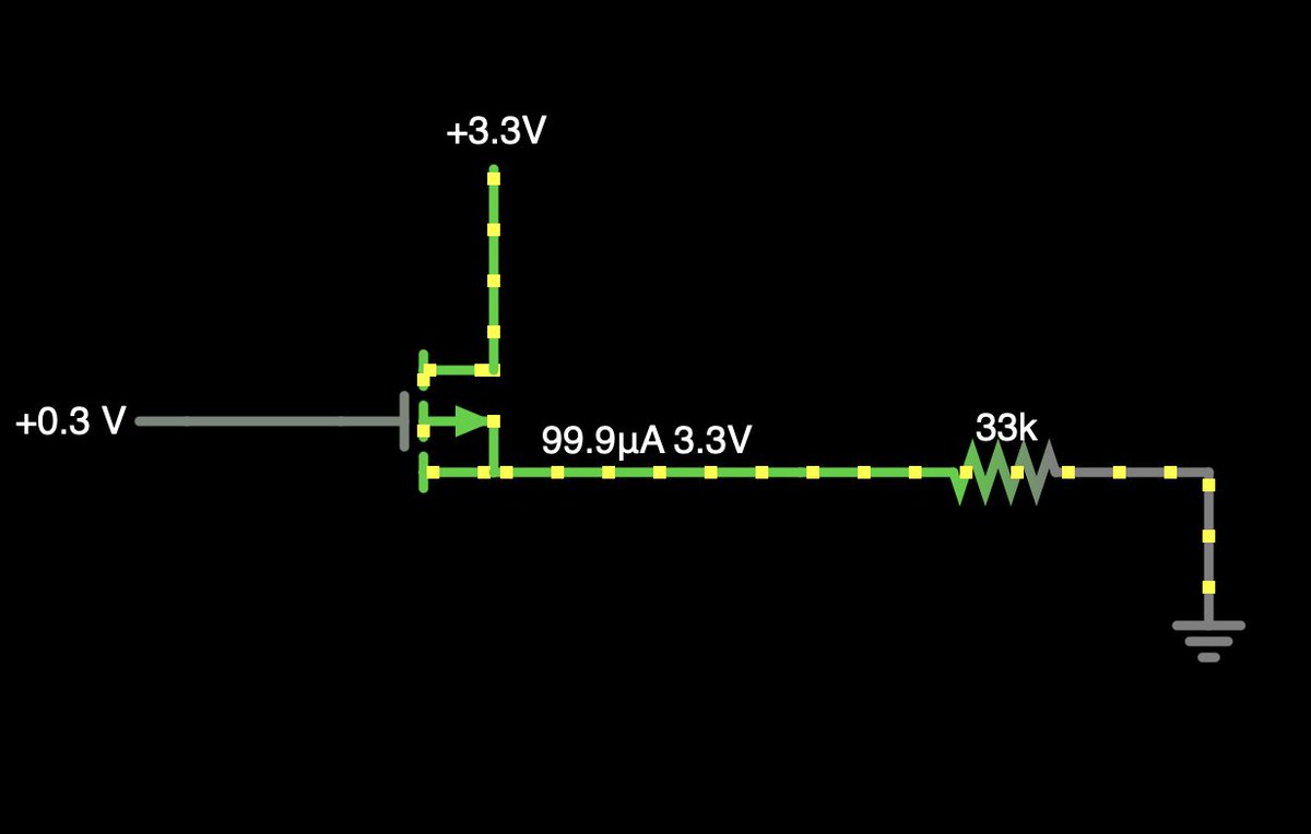
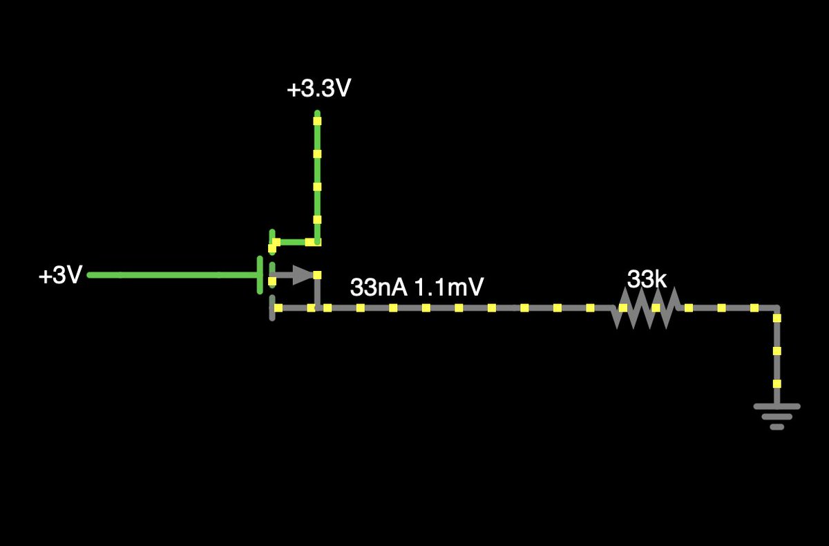
Crucially, this is fine for the battery circuit! Most of what we care about is getting current to flow from the battery to VCC without backpowering it, and avoiding the voltage drop of a diode. But for gating 3.3V power to my peripherals, I need to swap the source and drain.
(original)
Replying to @josecastillo
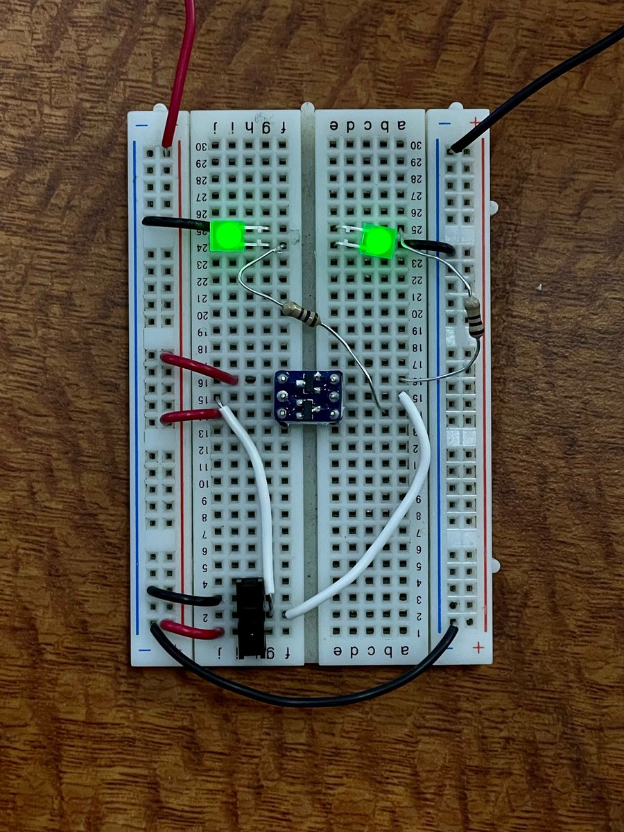
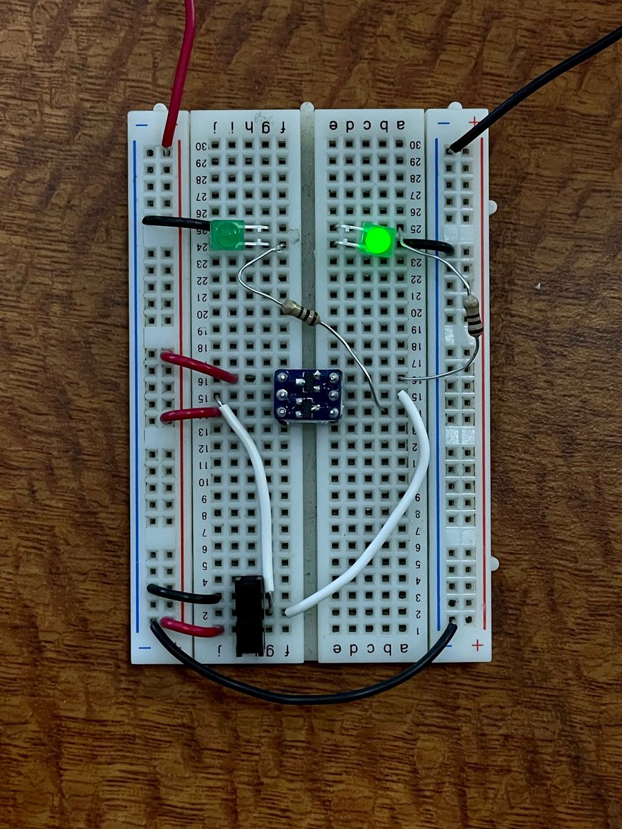
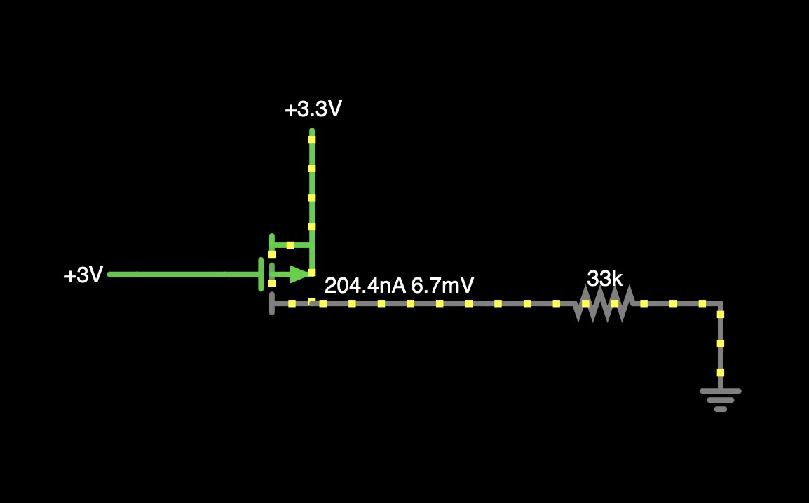
Pulling the gate high does cause current to stop flowing through the MOSFET, but it still flows (albeit at a lower voltage) through the body diode. That’s the circuit on the right: you can see that no matter where the switch is, the LED glows. It’s just slightly dimmer when off.
(original)
Replying to @josecastillo
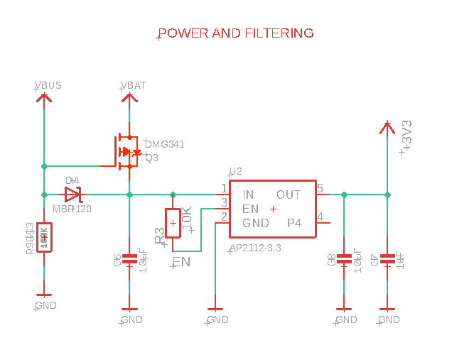
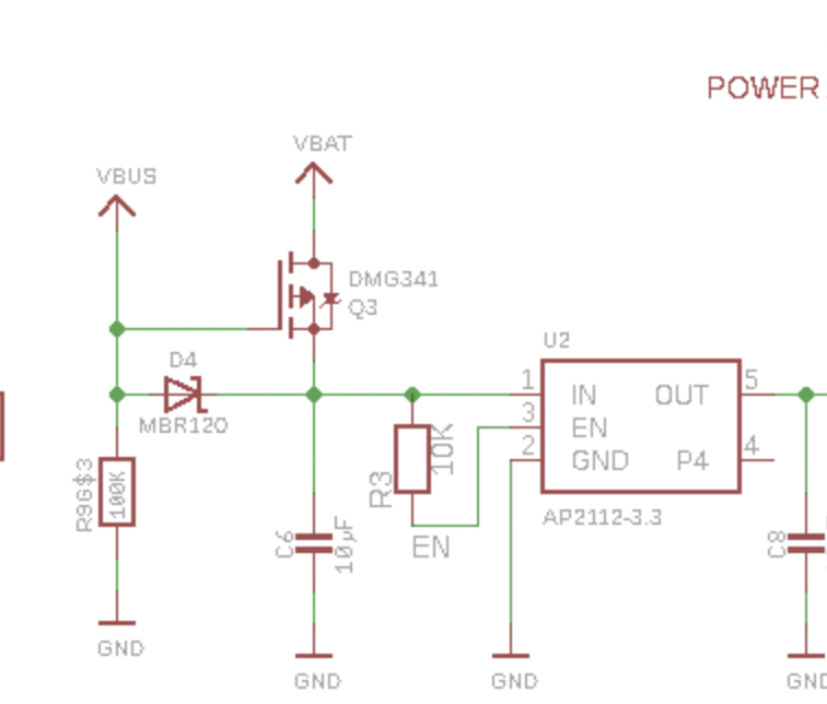
Adafruit’s Feathers use a P-channel MOSFET between the battery (drain) and VHI (source), and my assumption was that VBUS gated the power — that is to say, if VBUS is present, the MOSFET is preventing current from flowing. Which, sort of, but as I discovered, not exactly.
(original)
Replying to @josecastillo
The circuit in question. The observation: I have the source & drain pins swapped. Which he pointed out means that the MOSFET will always conduct through its body diode. The thing that’s weird is, I’d seen this circuit hooked up this way many times before… https://twitter.com/josecastillo/status/1534011403069177857
(original)
wow I have a million things to be doing today, but last night while posting about a new MOSFET for the book, @MathiasVerdon pointed out that I might have an error in my circuit. He was right, but of course I had to breadboard it myself this morning to better understand. A THREAD!
(original)
Replying to @MathiasVerdon
Intuitively this makes a lot more sense, and as a side note I had always wondered why the terms “source” and “drain” seemed backwards when I looked at the other version of this circuit. anyway thanks so much for offering your guidance!
(original)
Replying to @MathiasVerdon
aha so you’re right: I do have it backwards. The circuit works for gating power from a battery because we don’t care if the body diode conducts, and it protects the battery from being backpowered. but for this, I should connect 3.3V to the source, and my peripherals to the drain.
(original)
Replying to @dcelectr
TBH I don’t know if it’s a good design feature now… the Pi Pico datasheet says that we can draw up to an additional 300 mA from its 3V pin, which is more than the book’s peripherals will ever need. In hindsight I think that having that extra regulator might have been overkill.
(original)
Replying to @MathiasVerdon
I’ve also tested it myself on a breadboard and used it in other designs in the past, and it seems to do what it’s supposed to do; having said that, I’m totally open to understanding if I’m getting something fundamentally wrong.
(original)
Replying to @MathiasVerdon
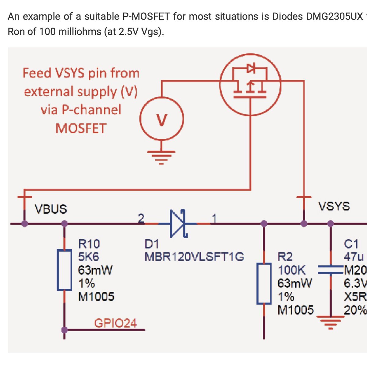
I will confess to being confused about this myself, because if I check “simulate body diode” in the simulator I see the same thing. Still I always see this circuit done this way, from Adafruit Feathers to the Pi Pico datasheet, so unless I’m missing something, I think it’s right?
(original)
Replying to @josecastillo
also to any new followers who are confused as to why i’m so far in the weeds on this: my practice isn’t just about building gadgets. it’s about explaining them: helping folks to understand what gadgets are made of, and empowering them to build technology that works on their terms
(original)
Replying to @josecastillo
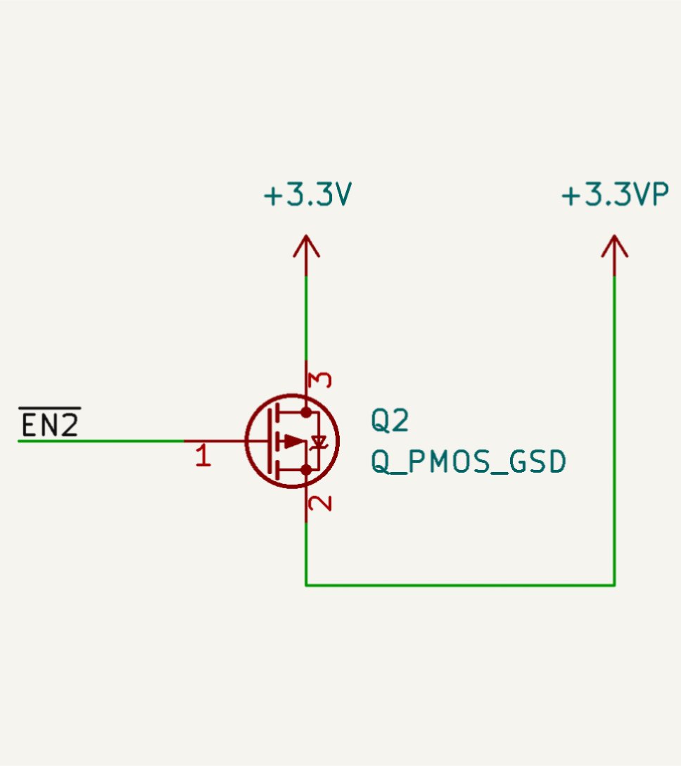
I’d previously been using a whole separate 3.3V regulator for this, and tying its Enable pin to this GPIO. Removed it because chip shortage, and because the Pi Pico’s buck/boost has enough power to spare to drive these peripherals. Nice to still be able to switch them off though!
(original)
Replying to @josecastillo
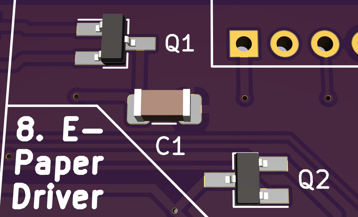
(Q2 is a P-channel MOSFET identical to Q1, but tied to a GPIO pin. the idea being you can drive it low to enable the 3.3VP power domain, which powers the e-paper display, microSD card and flash chip. but drive it high and it turns off their power entirely, like a plug in a drain)
(original)
board can have a little more mosfet, as a treat
(original)
Replying to @JeremyGrosser, @darianbjohnson and @MicrochipMakes
Great tip! Also now that I’m thinking about it more, I definitely see your point: if I don’t have a low power MCU available to me, a chip like this could help me to cut power to the whole gadget, while having just one button that the user could press to restore it.
(original)
Replying to @JeremyGrosser, @darianbjohnson and @MicrochipMakes
Might work if you’re waking only occasionally, but I played with putting the Sensor Watch into ultra low power BACKUP mode and waking from reset once a minute. The additional time spent setting up from the reset state negated the gains from being essentially off for that minute.
(original)
Replying to @darianbjohnson and @MicrochipMakes
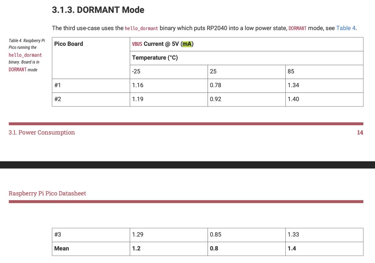
Well it might still be more than that — at least 180µA for the chip, plus the quiescent of the RT6150. But at least I won’t be burning anything else on the e-paper driver chip or the microSD. Pi Pico’s data sheet estimates DORMANT to be 800µA at 5V. I’ll have to test at 2.8~3.3V!
(original)
Replying to @darianbjohnson and @MicrochipMakes
unrelatedly: I’m glad you asked about this, because while explaining my power budget, it got me thinking about power gating my peripherals like the microSD, language chip and display. I think I can in fact get the book down to nothing more than the Pi Pico’s DORMANT consumption.
(original)
Replying to @darianbjohnson and @MicrochipMakes
In this case I’m just going to draw current from the Pico’s onboard buck/boost, which is the RT6150. Nice looking part, and shockingly quite in stock at DigiKey: https://www.digikey.com/en/products/detail/RT6150BGQW/1028-1260-1-ND/4733184
(original)
Replying to @darianbjohnson and @MicrochipMakes
I guess technically more like 800µA, because of the supporting circuitry around the RP2040 like the buck/boost. So I imagine a DORMANT book will draw about 1mA. But! A rechargeable AAA has a capacity of 1000 mAh, which is 10 times more than the 100 mAh coin cell in Sensor Watch.
(original)
Replying to @darianbjohnson and @MicrochipMakes
That’s just for the core processor; peripherals add to that. In Sensor Watch, the L22’s standby is 1.8µA, but with the LCD and RTC I get 6µA total standby budget. With the RP2040 book, I’m going to be starting at 180µA, and adding the quiescent current of two chips + the display.
(original)
Replying to @darianbjohnson
Alas, I would not; I’d be looking for something with standby current consumption under 10µA. In terms of a Cortex M0+, I think the @MicrochipMakes SAM L21 and L22 hit a sweet spot; the L21 can stand by as low as 1.2µA, whereas the RP2040’s DORMANT state only gets as low as 180µA.
(original)
Replying to @josecastillo
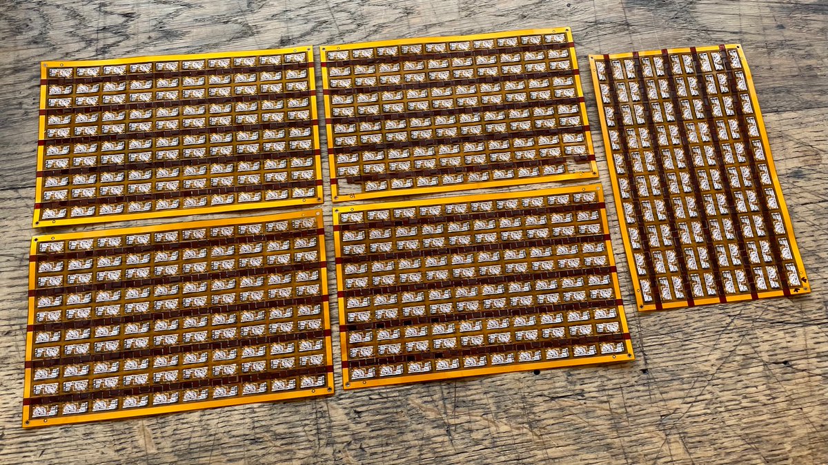
On the one hand, this is just five panels. You can count that on one hand. But it’s 500 boards, representing 1,000 component placements in 3.5 hours. I need to do 16 of these all told, so I sense I’ll be able to knock the rest out in one solid day of work.
(original)
Replying to @josecastillo
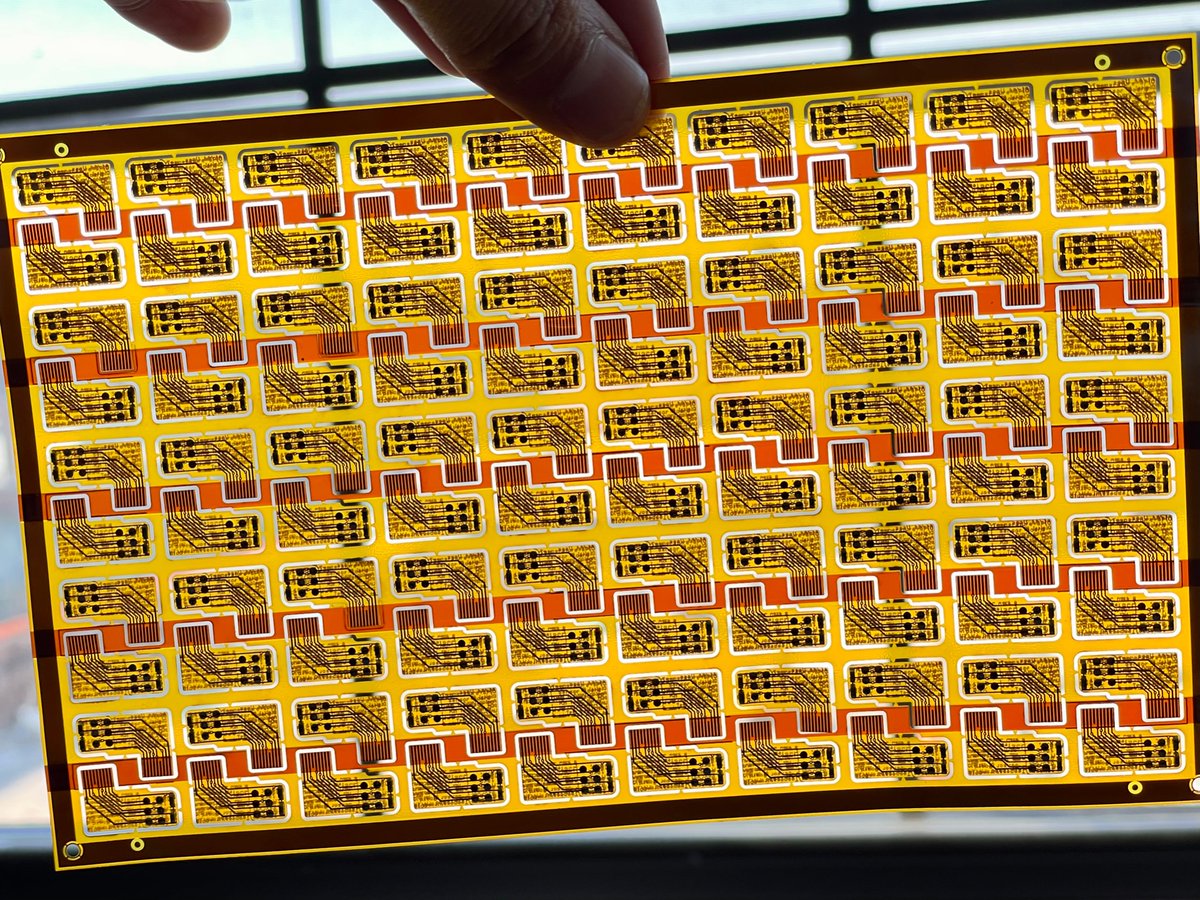
finished flex panel is ready for its close-up.
(original)
it’s time to make the doughnuts. Built 200 temperature sensors in this timelapse; aiming for 500 total today. @MakeAugusta is manufacturing all the Sensor Watch main boards, but when you get your temperature sensor, it’ll be because I placed it by hand and baked it, just for you.
(original)
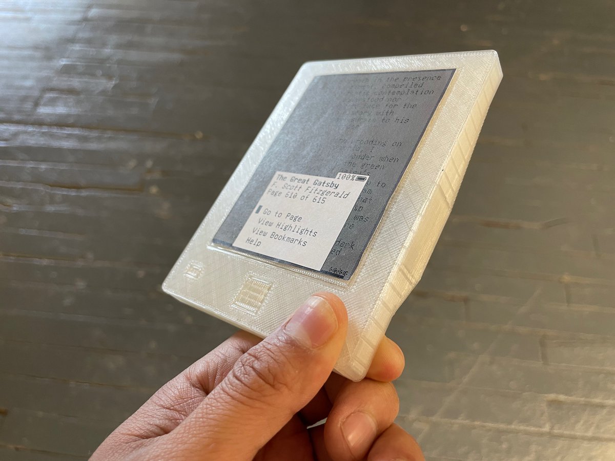
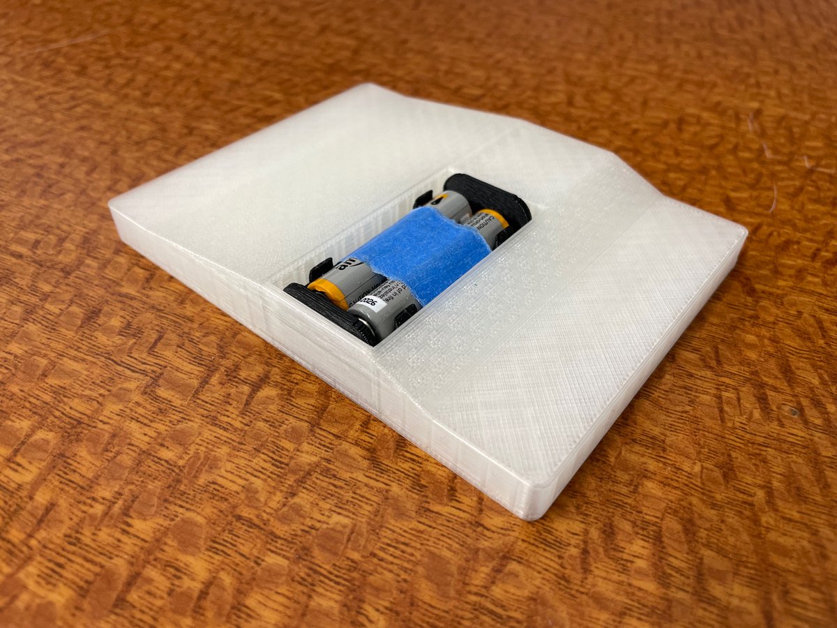
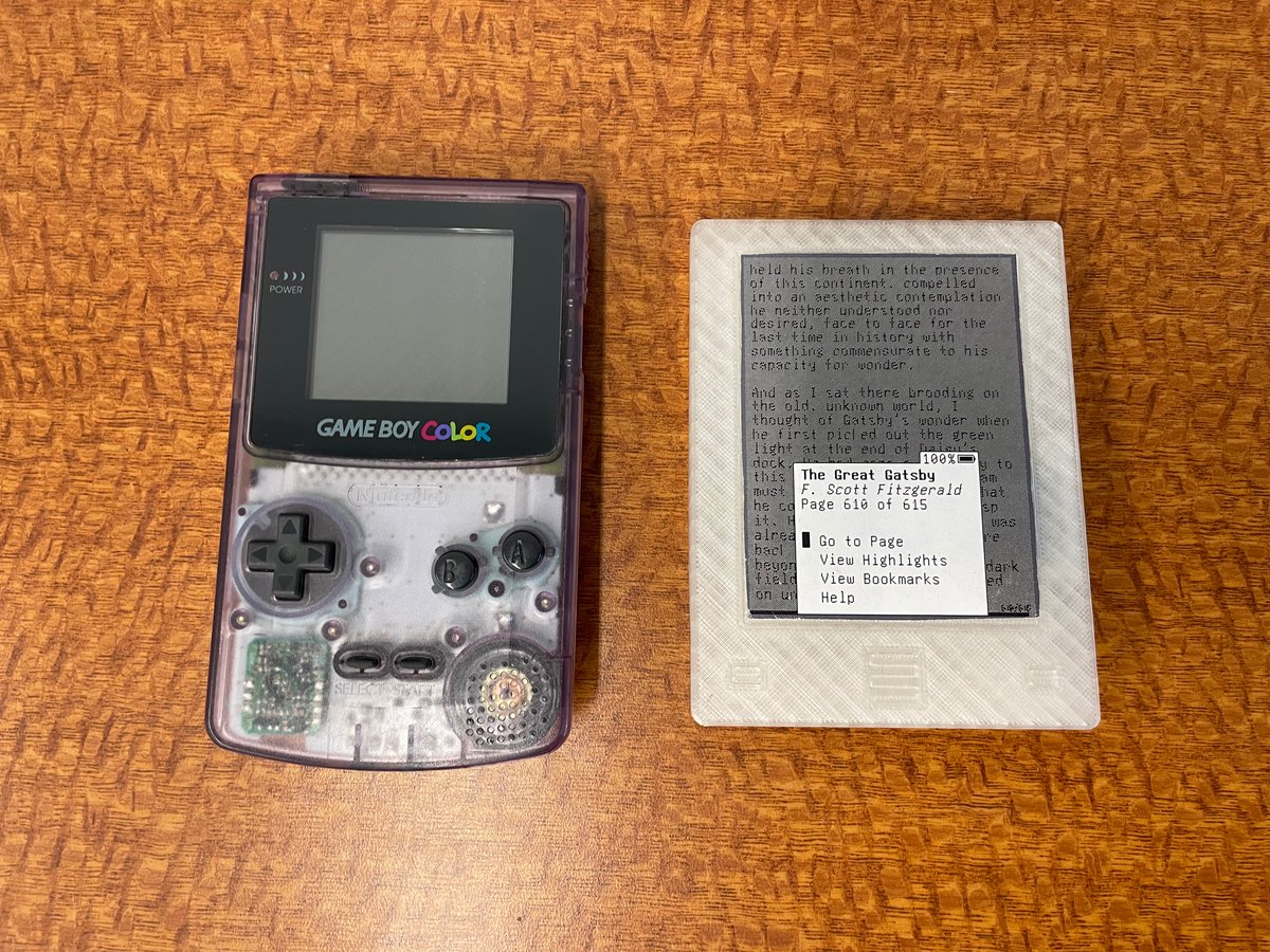
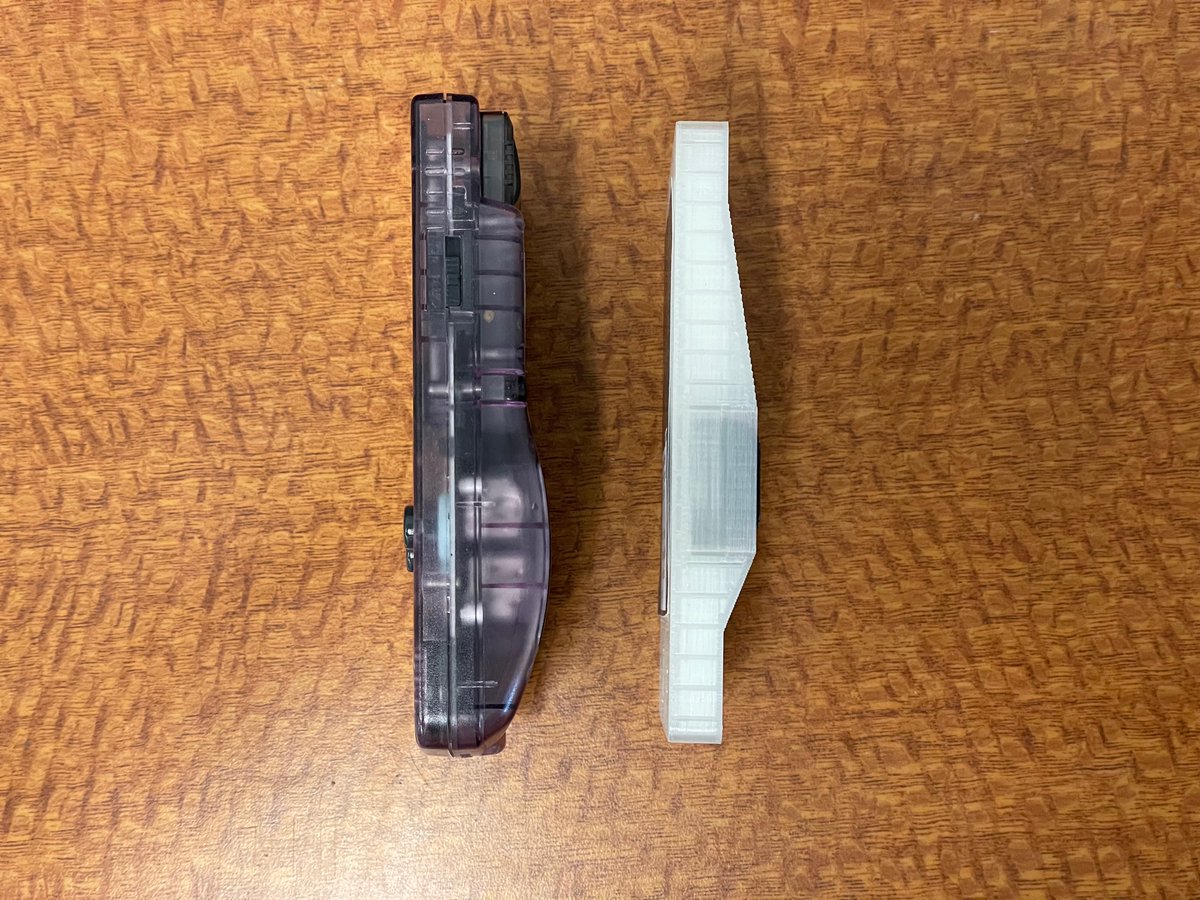
Y’know, after fidgeting with the new mockup for a couple of days, I don’t hate it! Here it is next to my old Game Boy Color. The ergonomics are wildly different, of course, but it feels like I’m wandering in a good direction. https://twitter.com/josecastillo/status/1533194874358583303
(original)
Replying to @josecastillo
Thanks to @nvuono for what looks like the answer! It seems to be a clone of the Keystone 1022: https://www.farnell.com/datasheets/1703881.pdf
(original)
Replying to @nvuono
oh would you look at that! It almost certainly is; thanks for this link! I somehow hadn’t run across this part in my searches :)
(original)
Replying to @darianbjohnson
TBH you could probably make use of the RP2040’s own RAM for this (there are six banks of RAM and you can power some down and keep others alive). I know FRAM might be lower power, but IMO dormant mode might be a little too power hungry to be reaching for those deep optimizations.
(original)
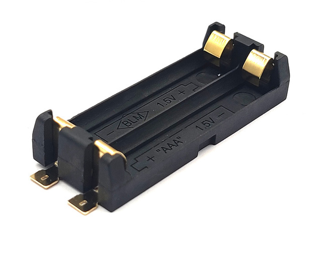
Electronics twitter folks: has anyone ever worked with 2xAAA battery holders like this from AliExpress? They seem to be ubiquitous there + on eBay, but I can’t seem to find a datasheet or even a basic drawing anywhere. Would love to make a KiCad footprint. https://www.aliexpress.com/item/3256802749229864.html
(original)
Replying to @ajbauer
the emperor has no body
(original)
Replying to @sinusoidal
It’s funny but this is all since I’ve moved to KiCad, and it’s bit me already once before. The default library’s QFN footprints have a subtle line instead of a corner at pin 1, and the diode issues you’ve mentioned. Stylish, I suppose, but I do prefer a clear and obvious mark.
(original)