Tweets
Replying to @josecastillo
UGH right, dang it. Going through last minute checks and I forgot: the SAM D51 has a bit of a glitch where the internal pull-up on RESET doesn’t work. Not much room left but I know where I’m going to put it; still not wild about it though.
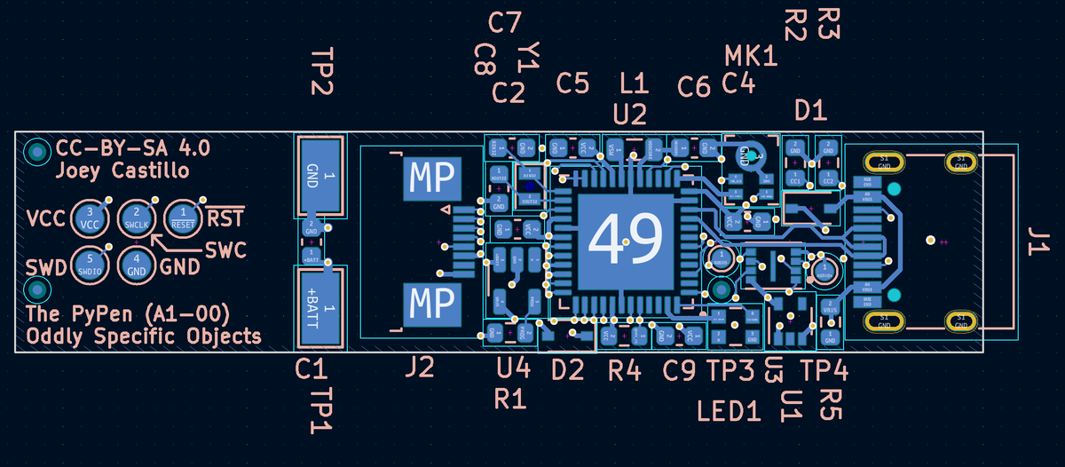
(original)
Replying to @josecastillo
Layers.
(original)
Replying to @josecastillo
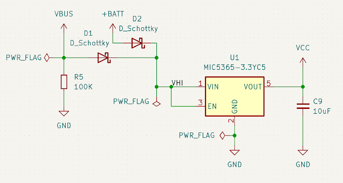
I think it’s about ready to order! One last-minute change: I realized I’d forgotten to connect VBUS to the regulator input, so the gadget would charge over USB but not function. So I had to tweak my design a bit. The pair of Schottky’s isn’t my fave, but it’s all I have room for.
(original)
Replying to @josecastillo
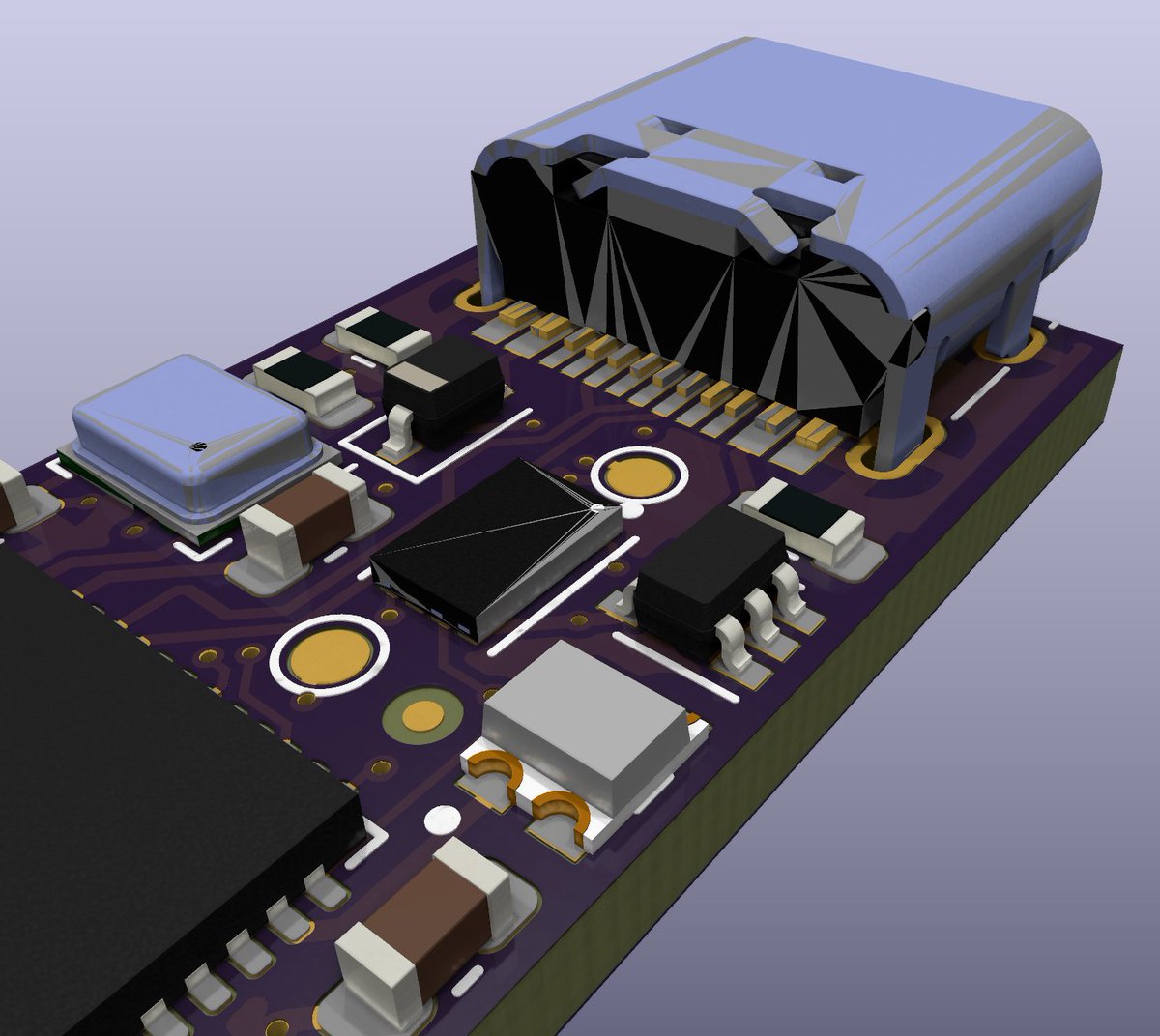
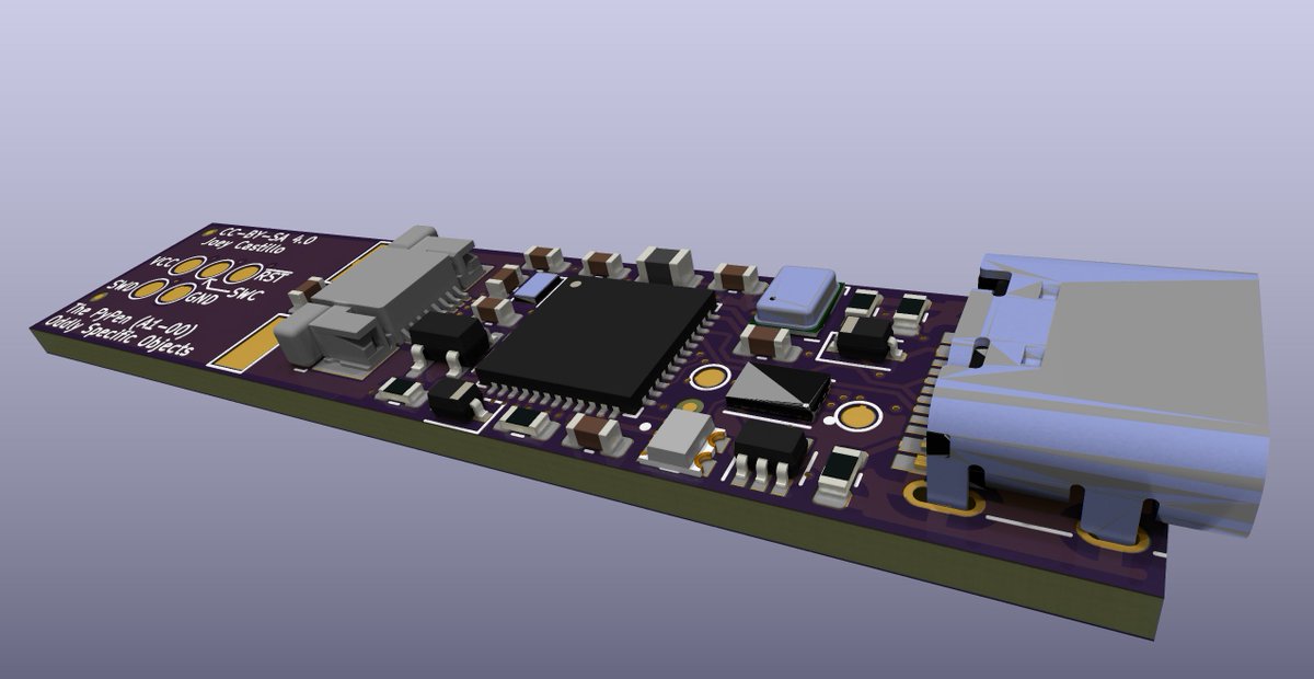
Question to any @kicad_pcb users out there: I imported some external STEP models to finish out a render of the board, but some of them exhibit this weird glitchy behavior when raytraced. Doesn’t seem to happen in normal 3D view (the last image). Just a bad model?
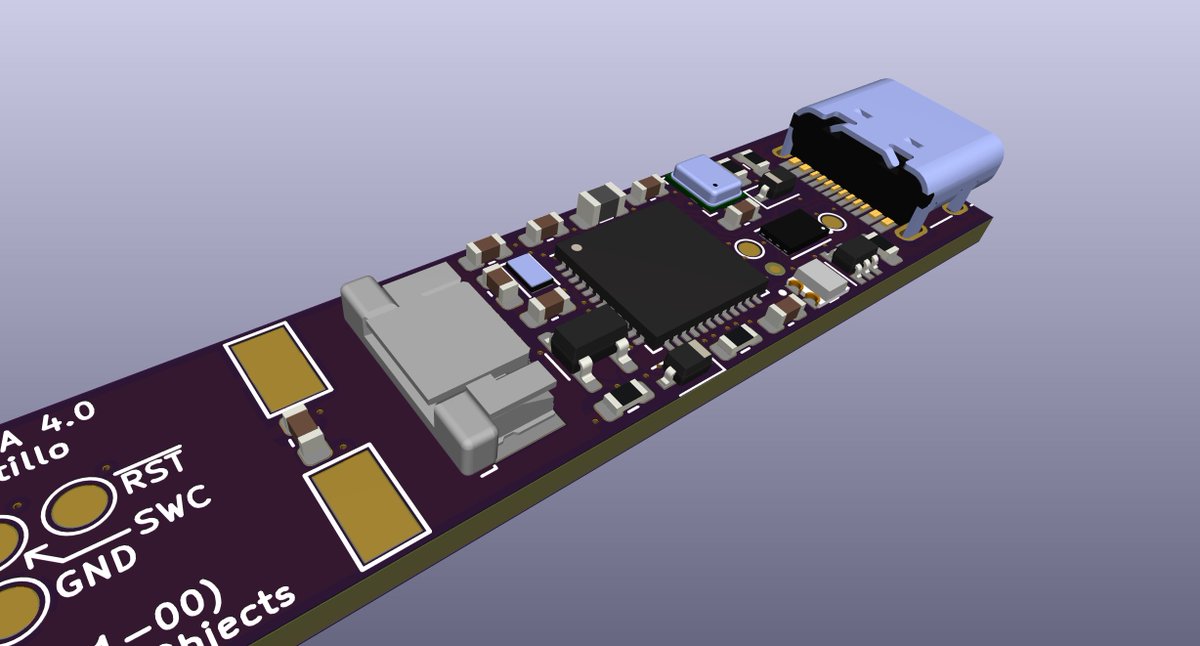
(original)
Replying to @josecastillo
I liked this one. Wordle 280 5/6*
⬛⬛⬛⬛🟨
⬛🟨⬛🟨⬛
⬛⬛🟩⬛🟨
🟩⬛🟩⬛🟩
🟩🟩🟩🟩🟩(original)
Replying to @james_hockridge
Didn’t try it but I should have!
(original)
#retrotech
(original)
Replying to @josecastillo
(original)
Replying to @enzinolombardi and @oshpark
Almost never; I actually find manual routing to be a soothing activity.
(original)
Replying to @josecastillo
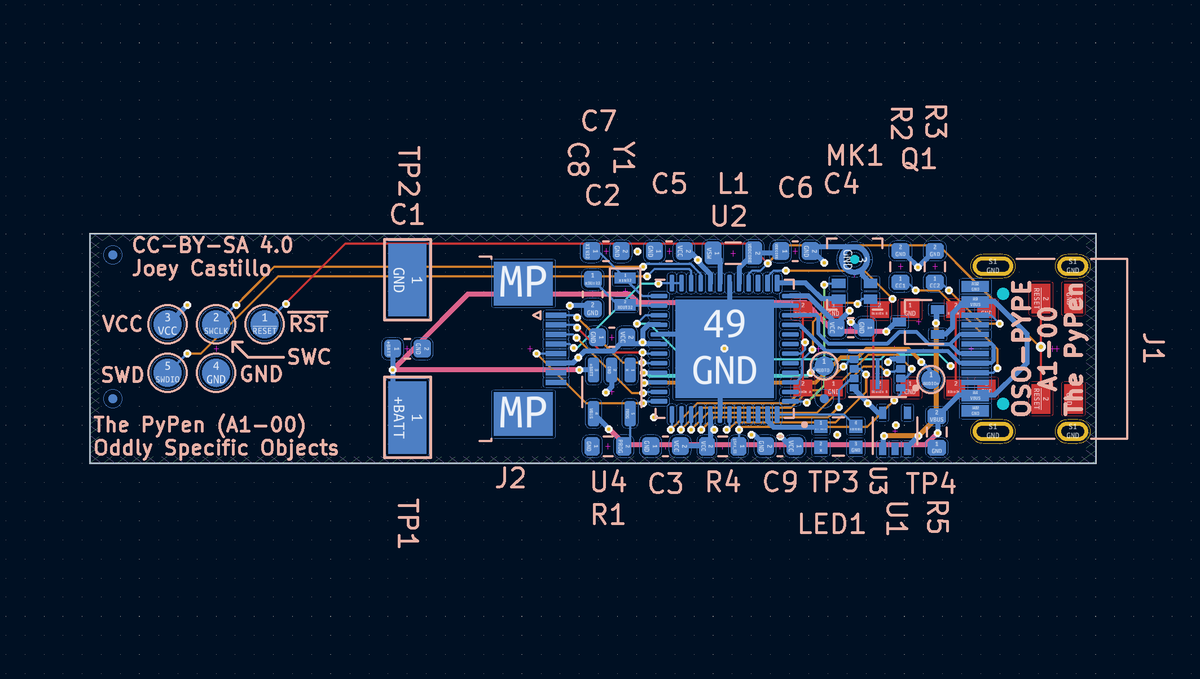
Unfortunately it looks like the screenshare was garbled the whole time. I may delete it. On the plus side: finished routing the gadget in just under an hour’s time! The 8 mil drill minimum on @oshpark’s 6-layer service really makes it easier (tho the 2 extra layers help too! 😃)
(original)
Replying to @jpoikela and @the_prepared
yeah I’m sorry, it looks like it was garbled to the point of uselessness for most of the stream. Disappointing.
(original)
Replying to @jpoikela and @the_prepared
It does not look like that on my end.
(original)
Replying to @jpoikela and @the_prepared
Huh, that does look pretty garbled, weird!
(original)
Replying to @josecastillo
OK: I sincerely doubt I’m going to finish today, but I have some spare cycles this afternoon so I’m starting to route the board! If you have questions, feel free to ask here and I’ll answer out loud in the stream; note however that I’ll be otherwise muted. https://twitter.com/josecastillo/status/1507437179575824384
(original)
Live from the workshop of @the_prepared in Brooklyn, New York: routing the PyPen! https://twitter.com/i/broadcasts/1mrxmagNabBxy
(original)
Replying to @josecastillo
well obviously that didn’t happen. Instead I managed to take a whole day off for the first time in a long time. Tomorrow all the paperwork is in order to make some significant progress on Sensor Watch, so maybe I’ll turn to routing this board over the weekend.
(original)
Replying to @josecastillo
Life on the Mesa. Wordle 279 4/6*
⬛⬛⬛⬛🟨
🟨🟨⬛🟨🟨
🟩🟩🟨🟩⬛
🟩🟩🟩🟩🟩
(original)
Replying to @josecastillo
Advisory: I’m taking a bit of a break from the shop today, but I may be online later tonight to route this beast. Or tomorrow. but tonight would be cooler. Might even try to live stream it.
(original)
Replying to @josecastillo
So close! I do like the new start word after all, but I may yet go back. Wordle 278 4/6*
⬛⬛⬛⬛⬛
🟨⬛🟩⬛🟩
🟩⬛🟩🟩🟩
🟩🟩🟩🟩🟩(original)
Replying to @deshipu
Yeah: on the G variant, there’s only one I2S clock pin, and it collides with the QSPI interface; you can only have one or the other. I decided to go with a PDM microphone instead.
(original)
Replying to @josecastillo
We can drive the AUDIO+ pin with the DAC and drive AUDIO- low to give the buzzer a true analog signal. OR: we can drive AUDIO+ and AUDIO- differentially with TC0 to get maximum volume out of a single tone. That’s pretty neat, and testament to the versatile the uses of these pins!
(original)
Replying to @josecastillo
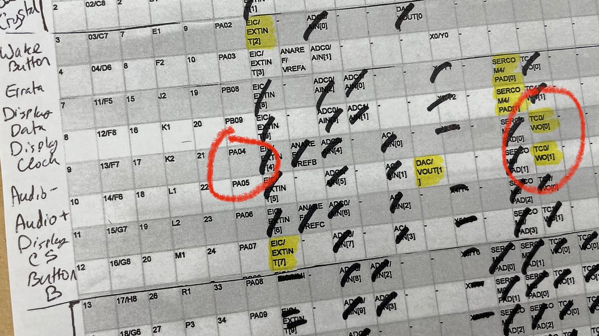
but! Right next to PA05 is PA04, and while it isn’t a DAC pin, it can do pulse-width modulation. Basically it can generate a square wave at an audible frequency — and what’s more it can do it in concert with PA05! Which means it gives us a second method for sounding the buzzer…
(original)
Replying to @josecastillo
This is useful for loudness: instead of seeing 3 volts and 0 volts, the buzzer sees ±3 volts. And the DAC on the SAM D51 can drive two pins in opposite polarities like this! Alas: I couldn’t use both DAC pins. The initial thought was to tie one side of the buzzer to ground…
(original)
Replying to @josecastillo
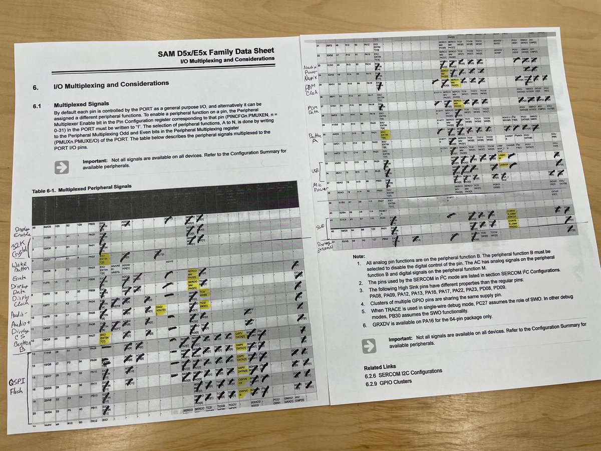
The final table. Which reminds me: there was technically one pin I forgot to talk about. I mentioned wanting to use PA02 for audio, but only being able to use PA05. That’s because I wanted to drive the piezo buzzer with a differential signal: one pin high while the other is low.
(original)
Replying to @josecastillo
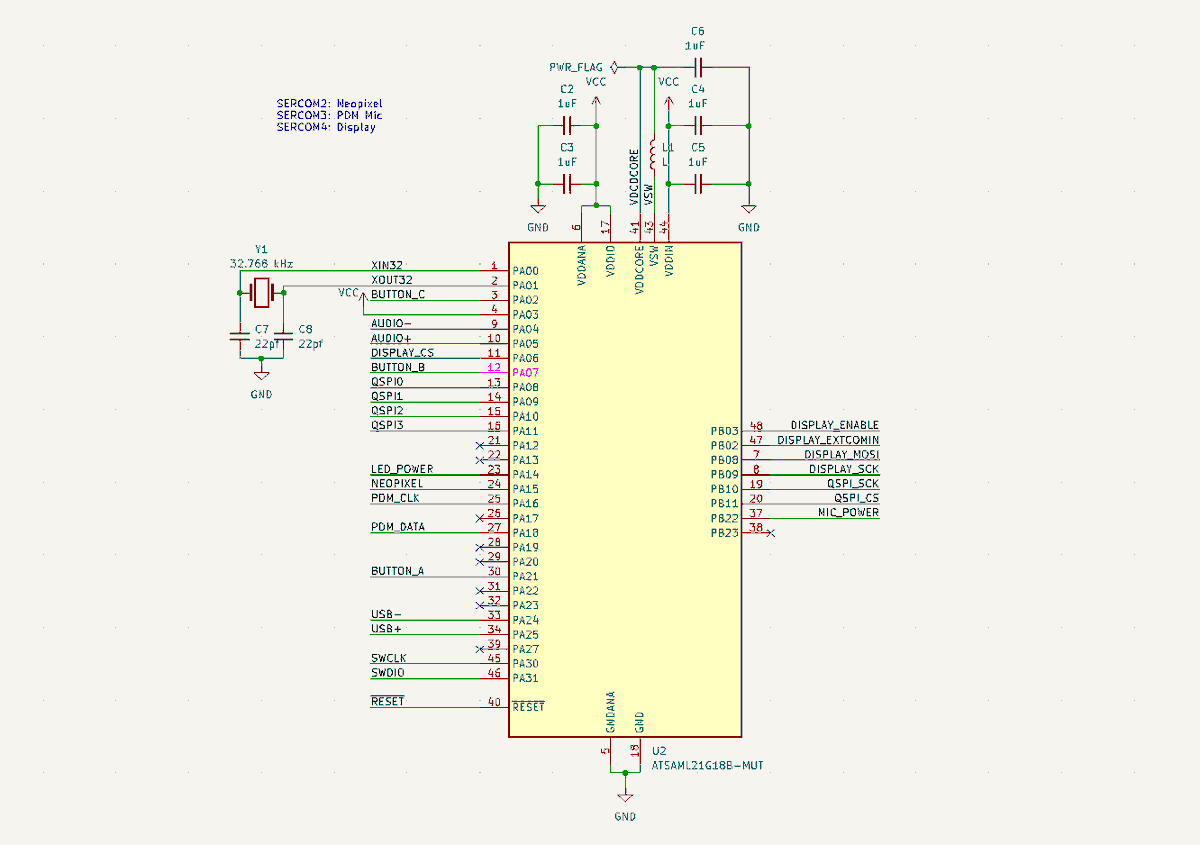
With that, folks: we’ve made a gadget! Well, I mean, mostly; I still have to actually wire up all of these connections. Still I hope this section of the thread helped to illuminate how those connections work, and perhaps inform how you might go about this in your own designs.
(original)
Replying to @josecastillo
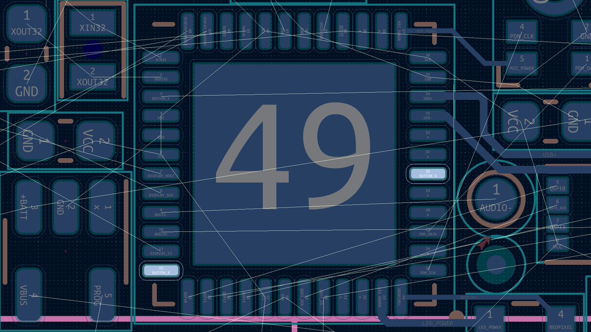
Since the wake button was already on PA02 (channel 2), I put button A on PA21 (channel 5) and button B on PA07 (channel 7). They feel easy enough to route, and if it becomes a headache, I can easily move them around; there are several free pins leftover.
(original)
Replying to @josecastillo
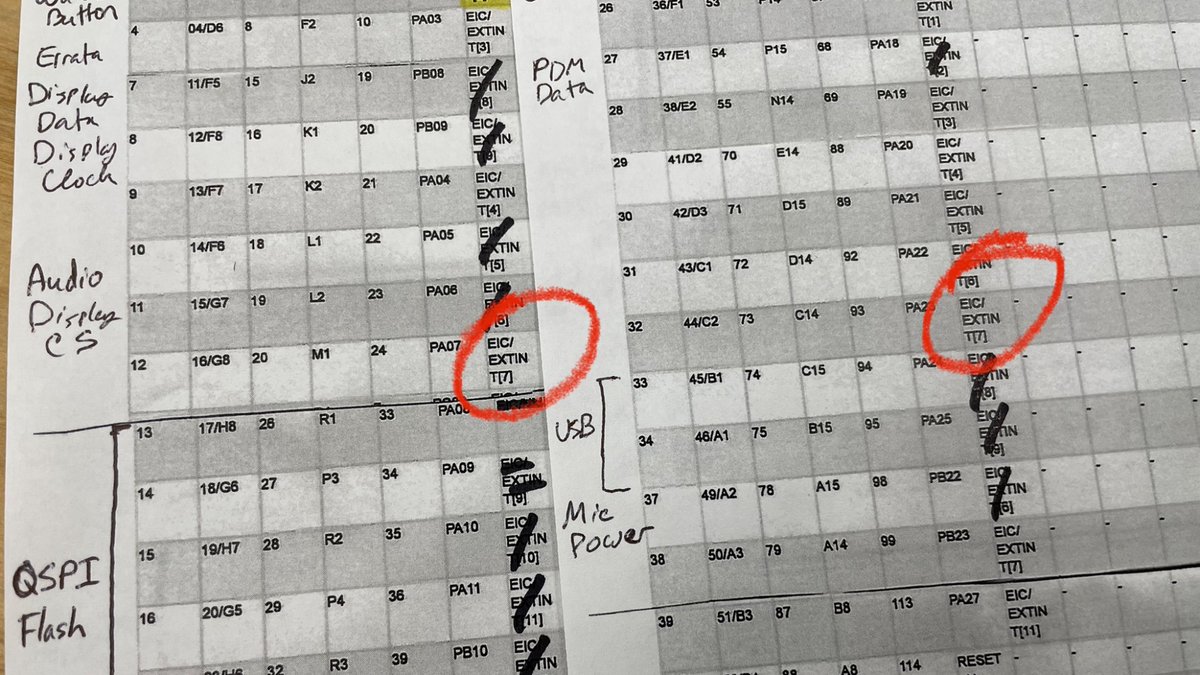
The SAM D51 has 17 interrupt channels, and some of them are duplicated across pins: for example, if you put a button on PA07 and another on PA23, they’d both be on interrupt channel 7, and it would be a headache trying to tell them apart.
(original)
Replying to @josecastillo
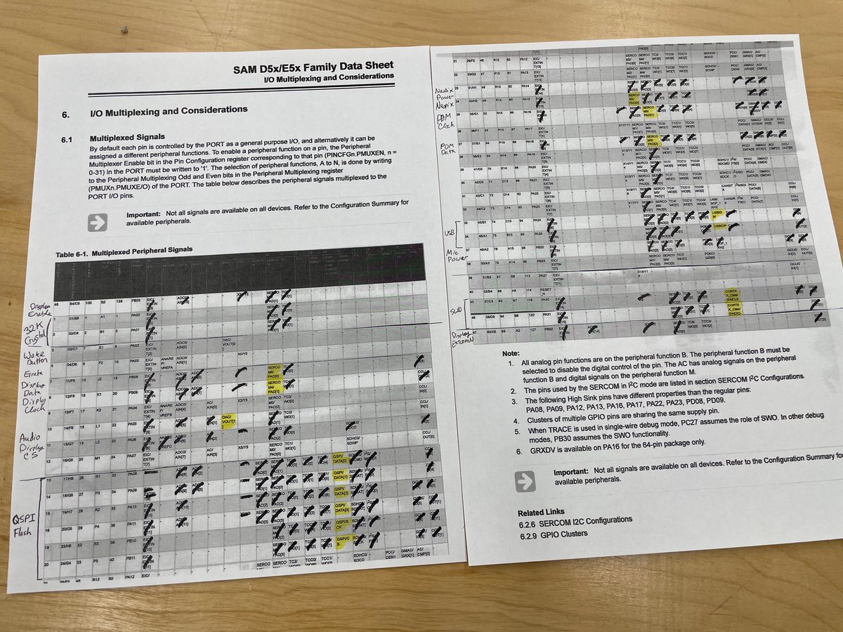
With that our pin mux table is starting to look pretty well filled out! At this point all we have left are the buttons. And for that, we need to think about interrupts. Ideally we’d like for buttons to be able to tell us they’ve been pressed, instead of polling them constantly…
(original)
Replying to @josecastillo
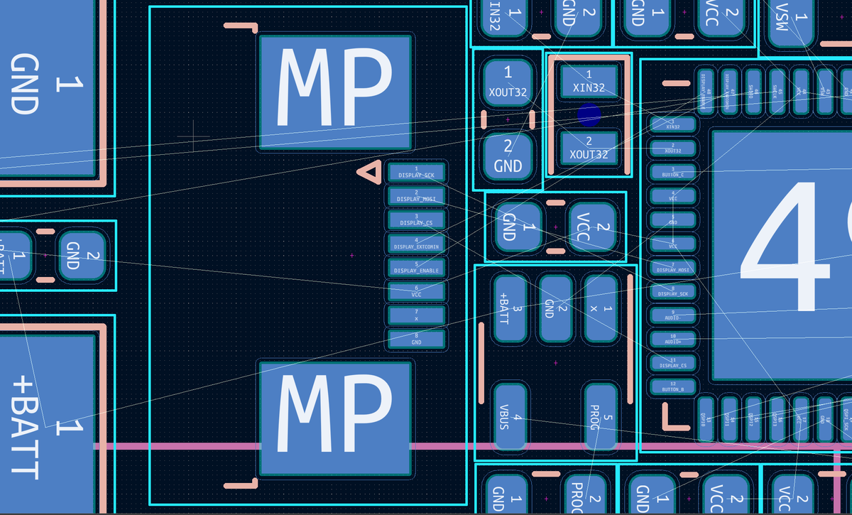
From here it starts to feel less like solving a crossword and more like solving a maze. The display connector is to the left of the microcontroller, so I figured I needed to pick some pins on the left side. That’s PB08/PB09 and SERCOM4 (which means our Neopixel is on SERCOM2 now)
(original)
Replying to @josecastillo
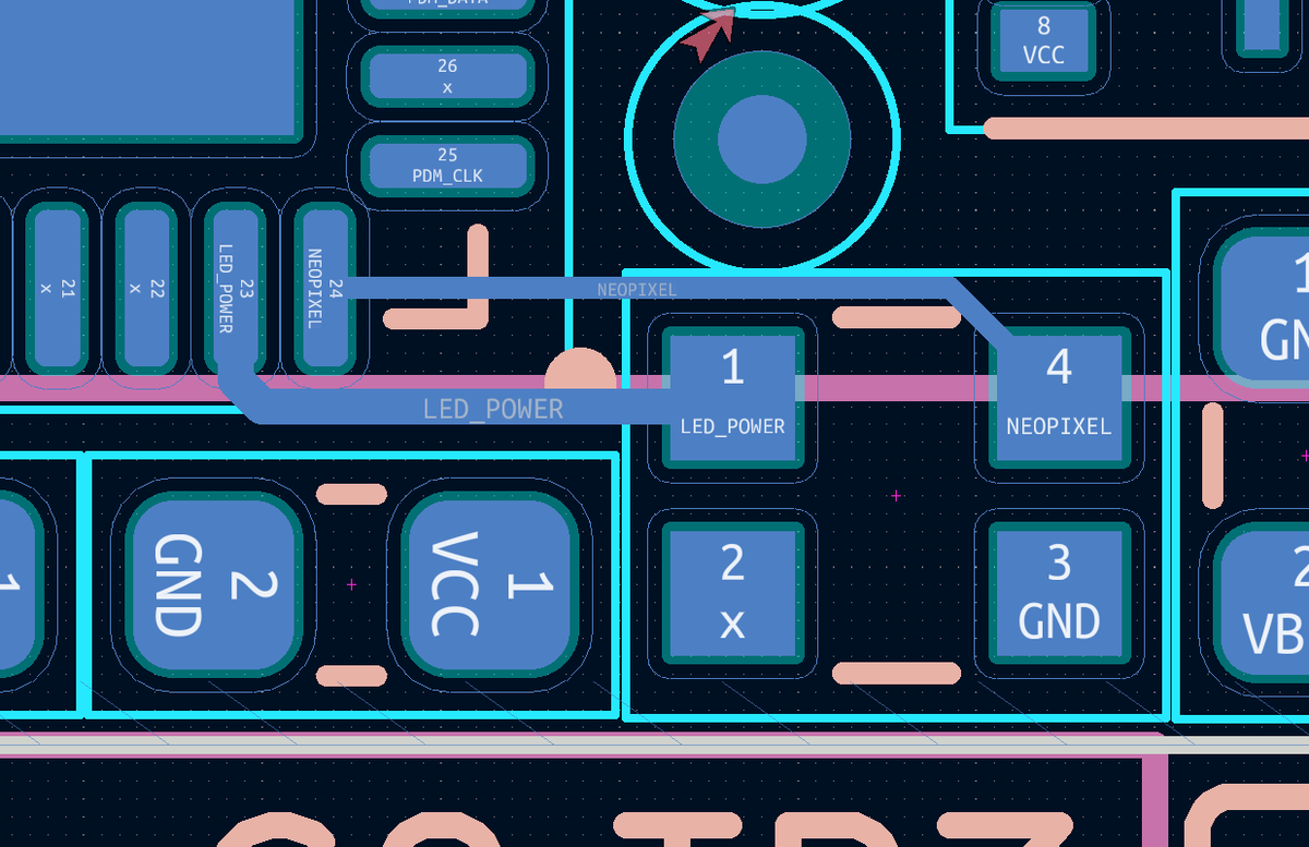
Did something similar with the Neopixel and its power, with the caveat that it can be useful to have the pixel’s data on a SERCOM’s SPI output pin so you don’t have to bitbang it. That’s two more pins claimed, and either SERCOM2 or SERCOM4 (we still have options).
(original)
Replying to @josecastillo
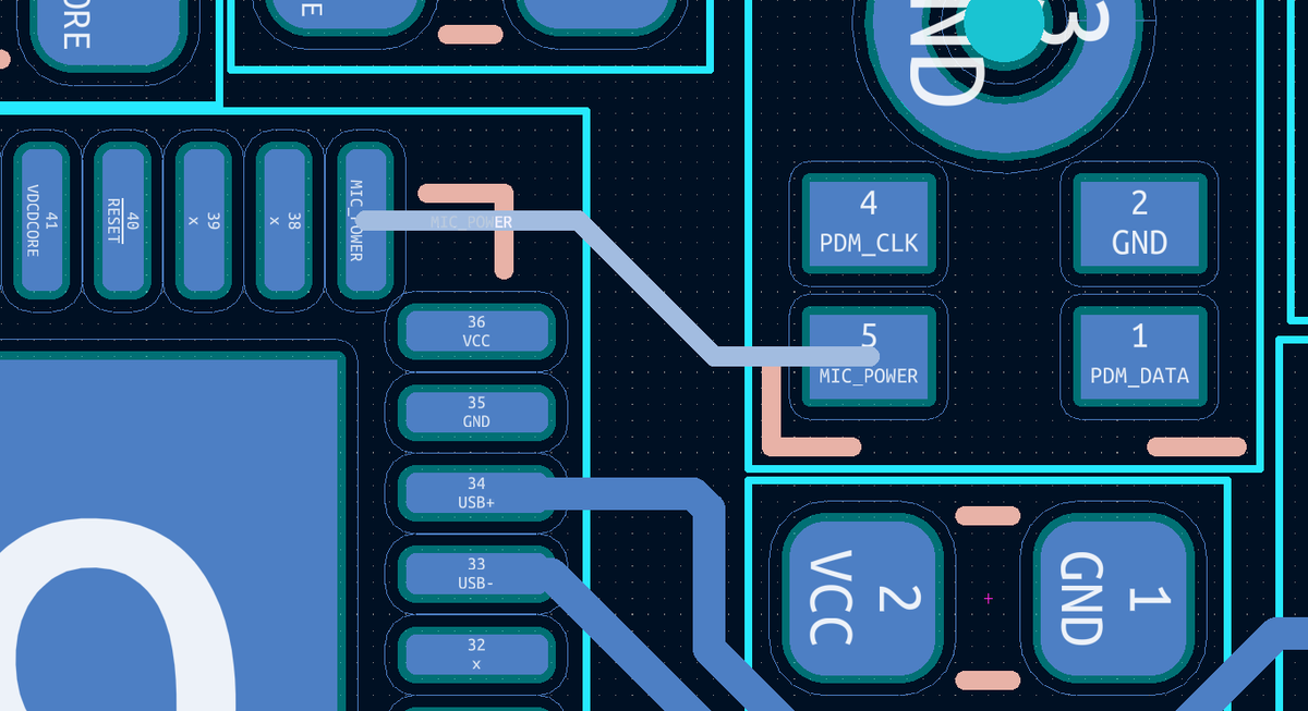
Anyway: at this point all my required choices are made, but they also may be challenging to route. Some things, like getting power to the microphone, don’t have any constraints; I can use any pin. Here it’s nice to look at the board and choose based on how easy it is to route:
(original)
Replying to @josecastillo
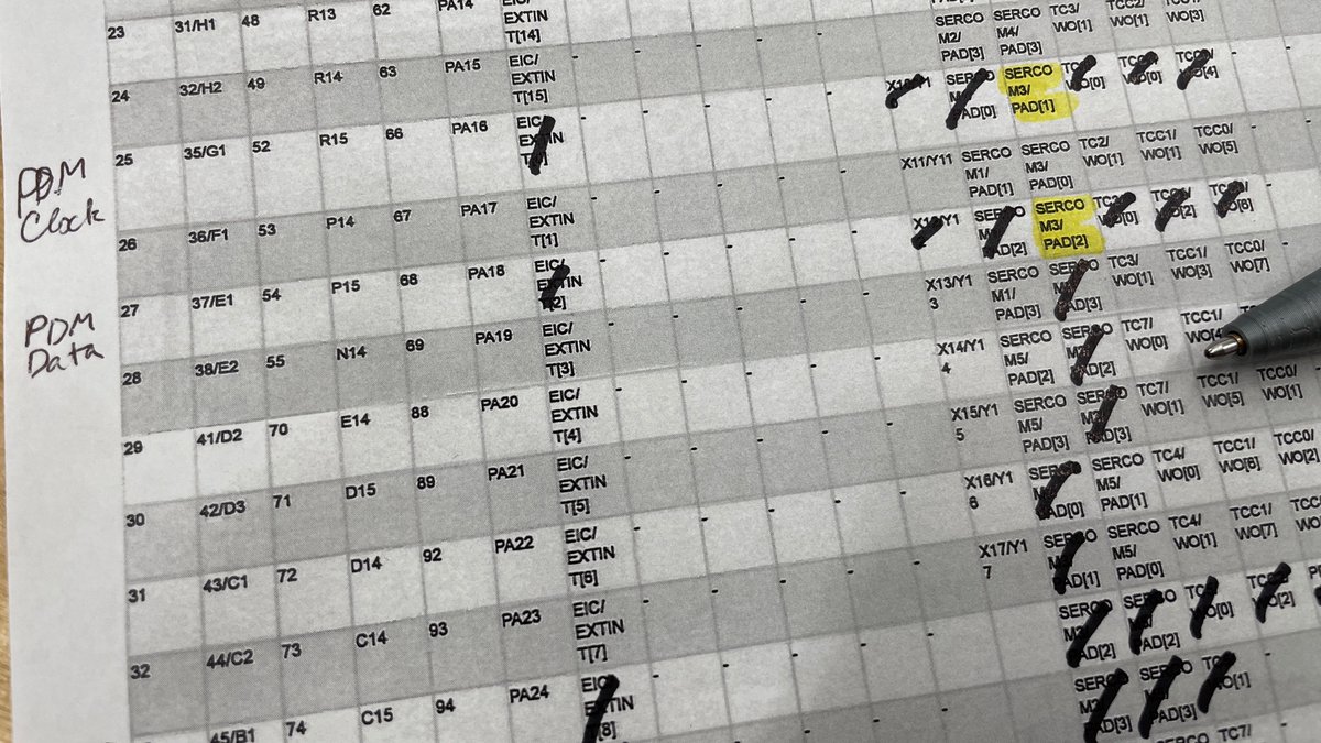
so here I pivoted to use a PDM microphone, like the Adafruit Edge Badge does. This lets me read audio data over a SERCOM, and tbh here I just copied their pin choices. SERCOM3 is now claimed for the cause — and that means I can scratch if off of every other line. It’s claimed.
(original)
Replying to @josecastillo
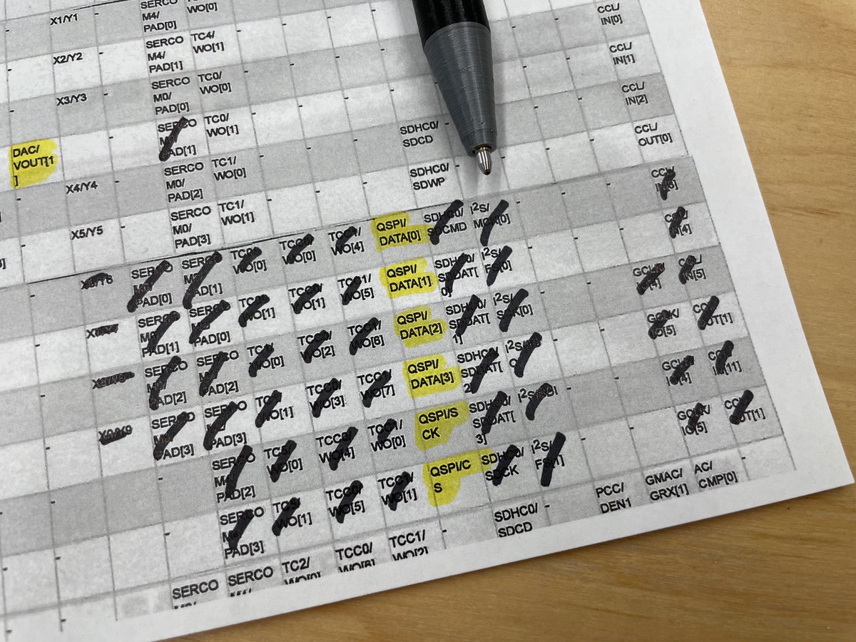
This is actually a point I reached today where I’d painted myself into a corner. I mentioned wanting an I2S mic, right? But here I realized I’d already scratched out all of my options for using the I2S peripheral. Unless I wanted to revisit my choices, that door was closed to me.
(original)
Replying to @josecastillo
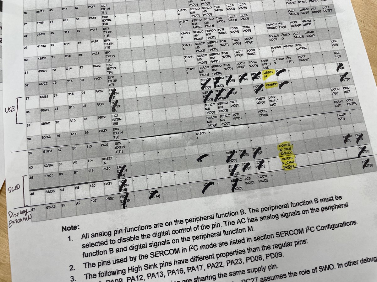
USB pins, debug pins, again: only one option each. Highlight the choice we’ve made; strike out the things we sacrificed to make it. With every choice we make, we close the door on other possibilities.
(original)
Replying to @josecastillo
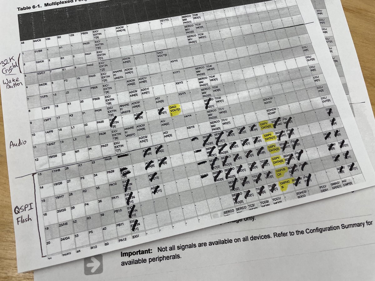
Next up: there’s a Flash chip on the board for storing your files. I’d like to use the SAM D51’s very fast QSPI interface for that, and there are only six pins that can do it. So those pins are claimed. (I also sometimes strike out the functions I can no longer use on those pins)
(original)
Replying to @josecastillo
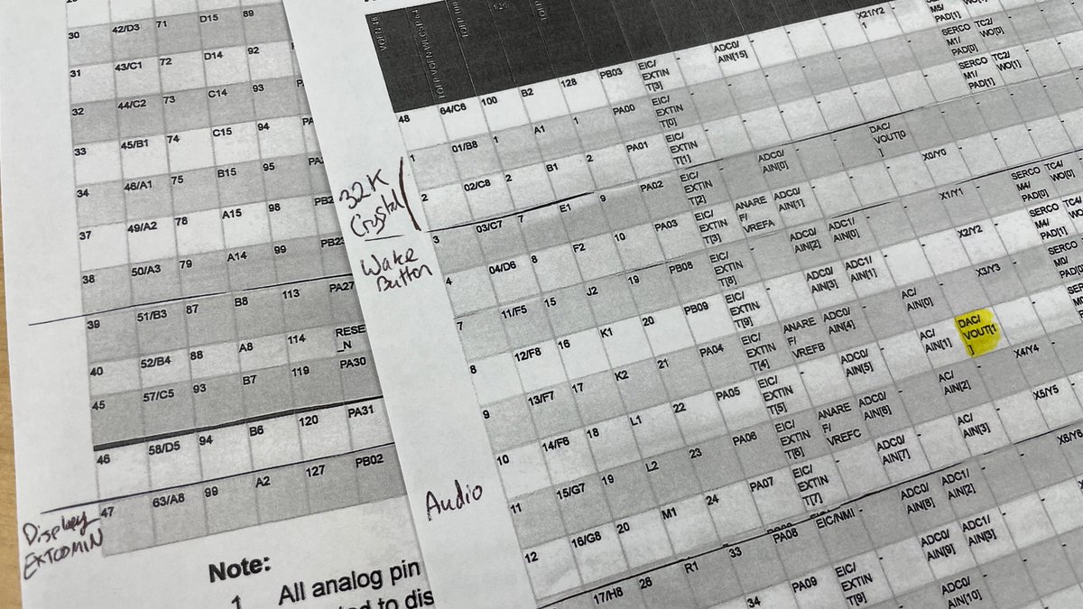
So now we’re getting somewhere. If we want a DAC — digital analog converter — for playing audio, there’s only one pin left for that, PA05. So I can claim it and highlight its function. At this point it feels a bit like solving a crossword puzzle.
(original)
Replying to @josecastillo
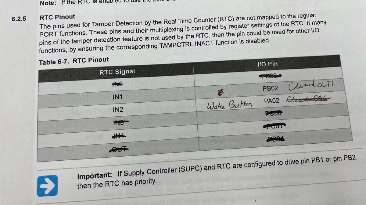
Next up: deep sleep. Waking from this mode is the responsibility of the real time clock, and we only get two pins for this. One of them was PB02, which we just claimed, so that’s out. The only one left is PA02, which I had hoped to use for audio, but it’s our wake button instead.
(original)
Replying to @josecastillo
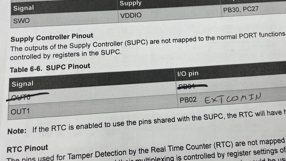
Similarly, I want to use the D51’s Supply Controller to generate a low frequency square wave (EXTCOMIN) on one of its output pins. We only have one of those pins on the G variant, so pin PB02 has its assignment set in stone.
(original)
Replying to @josecastillo
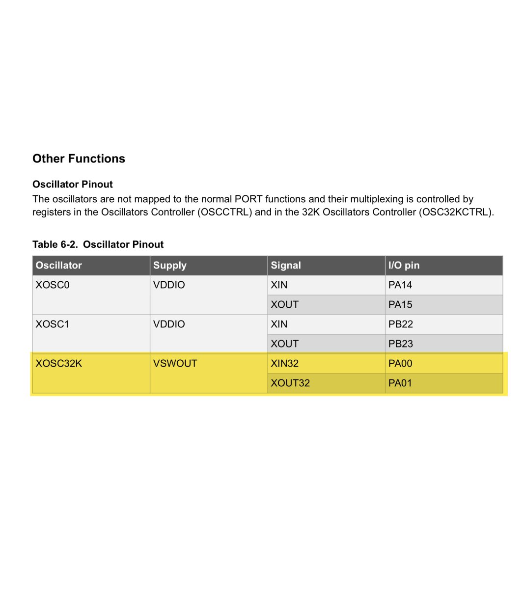
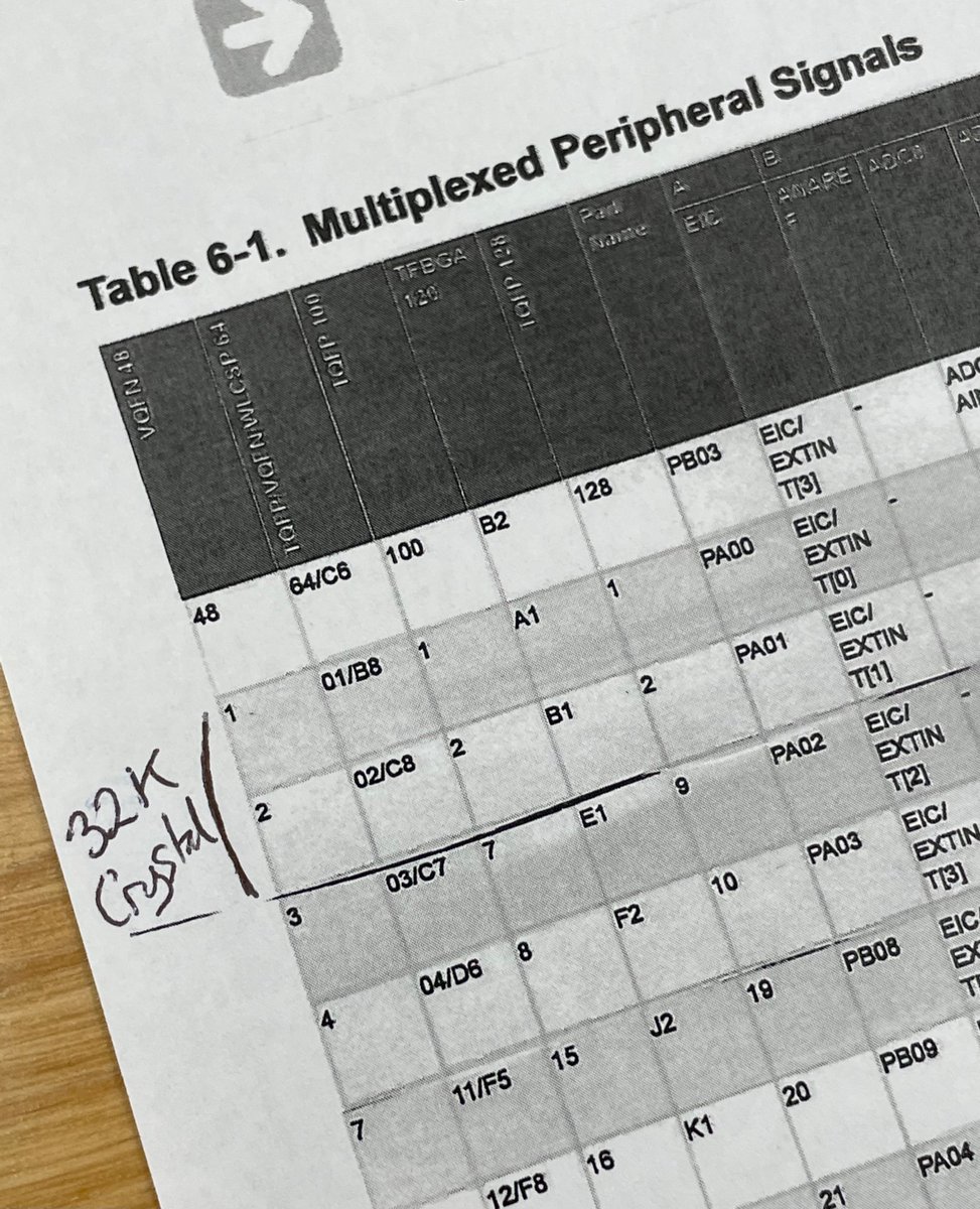
So there are a few pins you don’t get much of a choice about. For example: the SAM D51 supports a 32 kHz crystal oscillator for timekeeping. That oscillator has to be on pins PA00 and PA01. So those are locked in.
(original)
Replying to @josecastillo
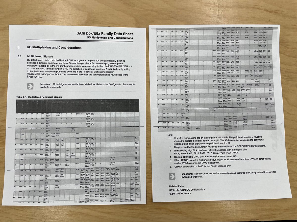
But today’s bit of process sharing is about one of my favorite parts of designing a gadget: pin selection. It always starts with a table like this, listing all the pins on a chip and all the different things they can do. This is the part where you choose which ones do what.
(original)
Replying to @josecastillo
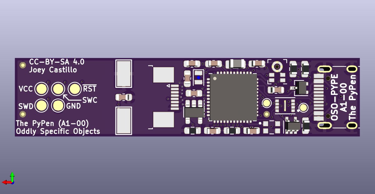
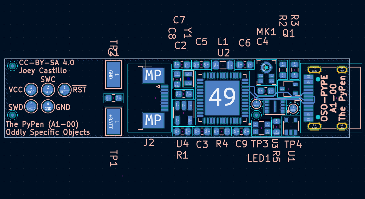
Well, it fits — with all 0603 passives! Will it route? that’s a very good question. This is without a doubt going to be a six-layer board, which would make it $15 for three from @oshpark.
(original)
Replying to @deshipu and @adafruit
One cannot steal that which has been shared-alike-4.0 :)
(original)
Replying to @deshipu
I’m using the ROHM BU9796AMUV! This idea came up on seeing @adafruit’s Great Search a few weeks ago, where this part came up. Affordable and simple to work with; the one downside is that it has no address pins, so you can only have one per I²C bus. https://www.youtube.com/watch?v=788EQXQLdMk
(original)
Replying to @josecastillo
(That’d be this Hello World demo)
(original)
LCD FeatherWing shout out in this week’s Python on Microcontrollers! I forget if I mentioned it in the thread, but that “Hello World” demo was all #CircuitPython; it’s so quick to get up and running and talking to an I²C device, it’s the tool I reach for first. https://twitter.com/adafruit/status/1506624569976795148
(original)
Replying to @josecastillo
Still feeling out the new start word. I think it necessitates a change in strategy… or a change back to my previous word. 😬
Wordle 277 5/6*⬛🟩⬛⬛⬛
⬛🟩⬛⬛⬛
⬛🟩⬛⬛⬛
⬛🟩🟨⬛🟩
🟩🟩🟩🟩🟩(original)
Replying to @SianaGearz and @fpgahelper
This could be the way! Test pads make for a minuscule PCB footprint, and I can direct drive a piezo from the DAC pins. There might just be room in the enclosure for something like this: https://www.digikey.com/en/products/detail/db-unlimited/P08080-1/9990567 (tho I’ll have to learn some things about springs…)
(original)
Replying to @fpgahelper and @SianaGearz
It would! Alas, my parts-fu hasn’t been able to find a surface mount piezo buzzer small enough to make sense. Unless…
(original)
So this is why toner is stupid expensive. https://twitter.com/azonenberg/status/1506403539223949315
(original)
Replying to @SnepOnSecurity
01005! Yea you have more experience than I do, and tbh I’m not usually wild about dealing with more than a couple of 0402’s. I don’t think I could call it a DIY project with a straight face if it had more than a fingertip’s worth of parts that tiny.
(original)