Tweets
Replying to @mishkathebear
clipped in with a CR1025 coin cell! Power pad on top, ground on bottom… haven’t figured out the metal piece that does the job yet, but there’s a cave painting of my thinking on it 2mm tall on the backside of the board :)

(original)
Replying to @josecastillo
other changes from the version I shared yesterday: swapped VCC and ground connections (which makes more sense tbh), moved the interrupt from reset to a GPIO pin (seems safer), and fixed the LED footprint (which had green and blue pins swapped). updated design files soon.
(original)
Replying to @josecastillo
as someone once said: if a thing like this is worth doing, it’s worth doing right.
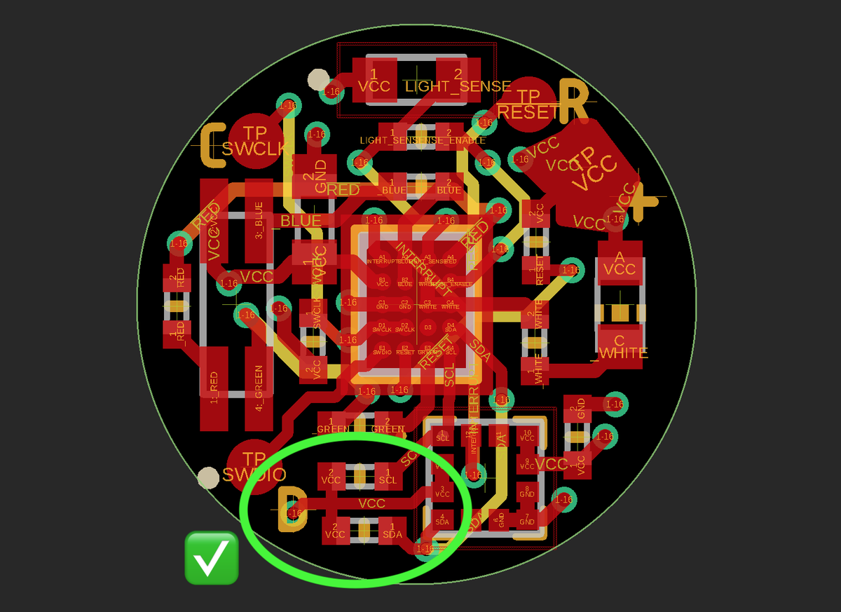
(original)
Replying to @josecastillo
haha i don’t even have an 0201 footprint in my library
(original)
Replying to @josecastillo
LOL, there is no way. short of moving to 0201’s… 🤔
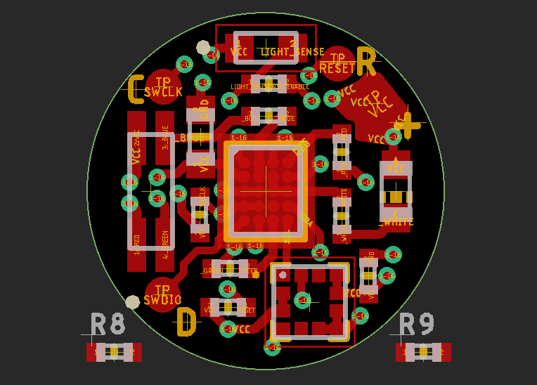
(original)
Replying to @josecastillo
actually wait, dang. last minute check before ordering: I forgot the I²C pull-ups. Wondering if I can get away with using our internal pull-up resistors. They’re 40kΩ, trace lengths are short, and I only have one gadget attached. maybe I can swing it if my speeds aren’t too high?
(original)
Replying to @josecastillo
actually, scratch that: next step is ordering some boards. Leap of faith, but not a huge one; $9.60 for three six-layer boards from @oshpark. I have faith that I’ll be able to get my hands on some of these chips someday. (also: assembly instructions right there on the backside!)
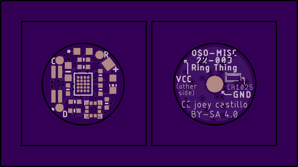
(original)
Replying to @josecastillo
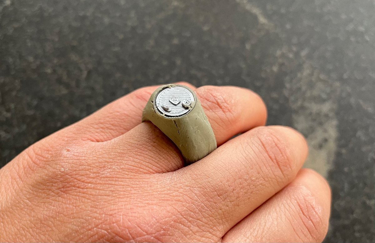
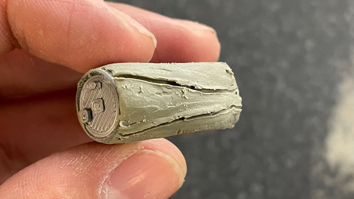
borrowed some modeling clay from a neighbor; it’s more material, but this actually looks nicer and feels marginally more wearable. Next step in my head involves subtracting some stuff, slimming down the backside.
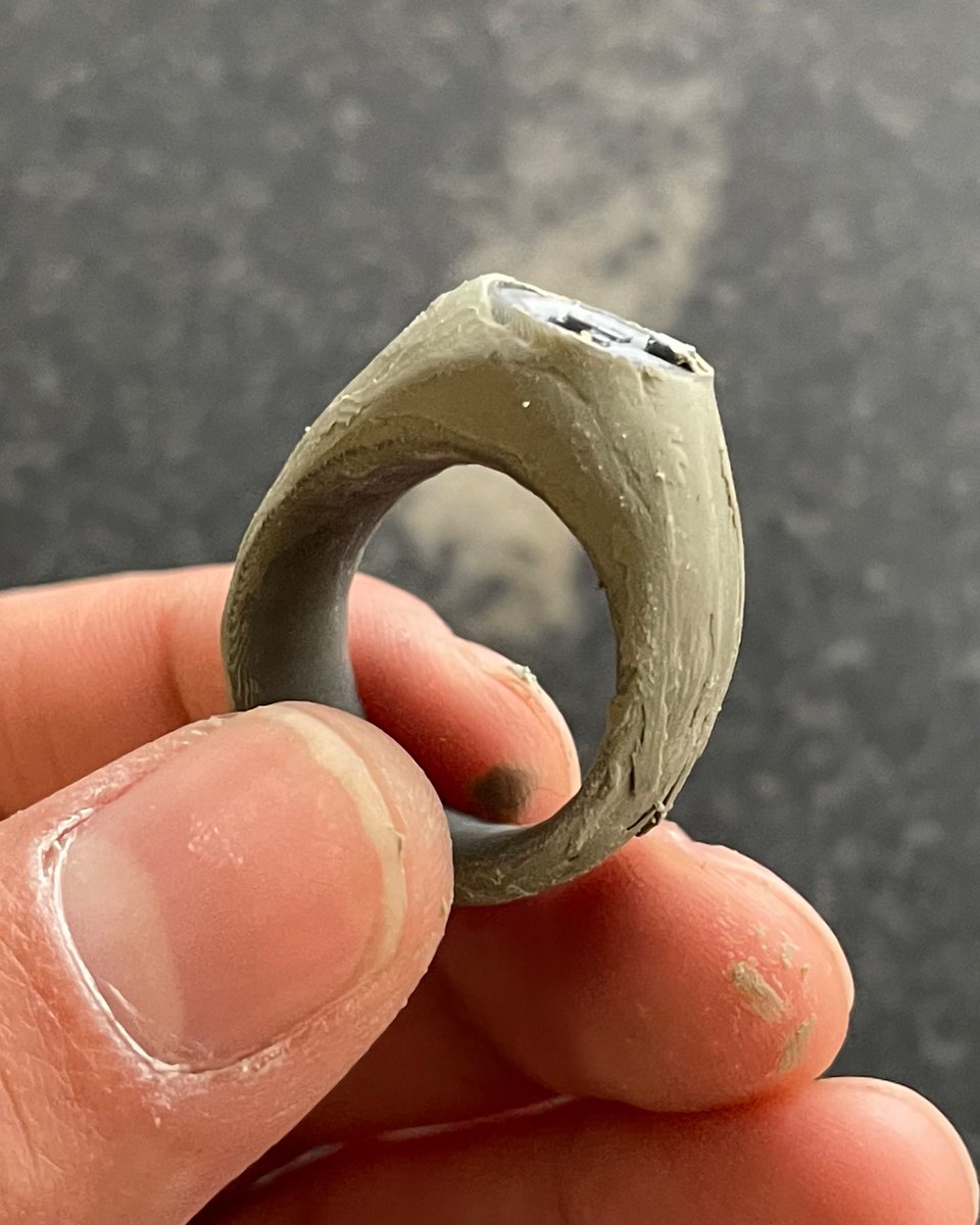
(original)
Replying to @jamesvasile
hah I’d love to! right now I’m still trying to figure out how to do a one of these 😬
(original)
Replying to @josecastillo
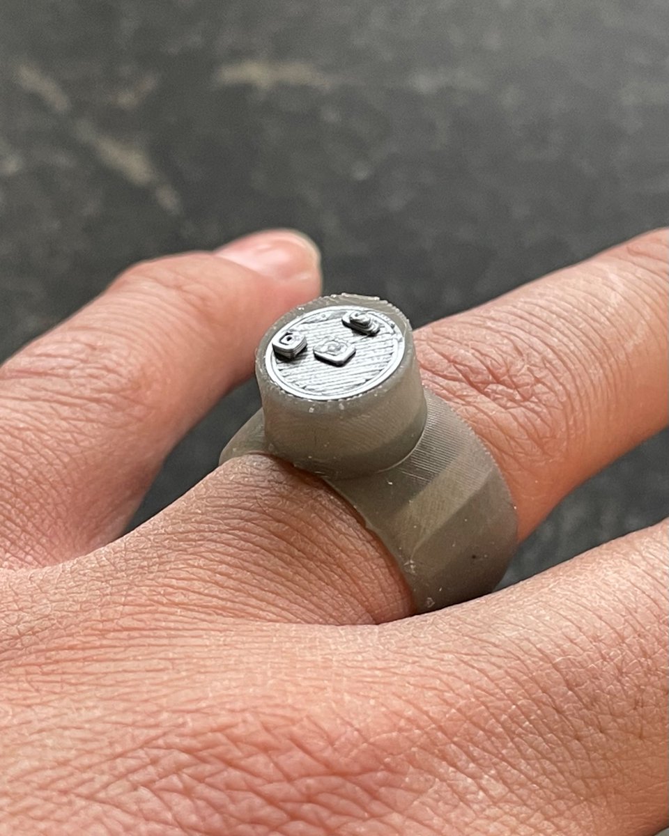
this is absurd. it shouldn’t exist.
I have to build it.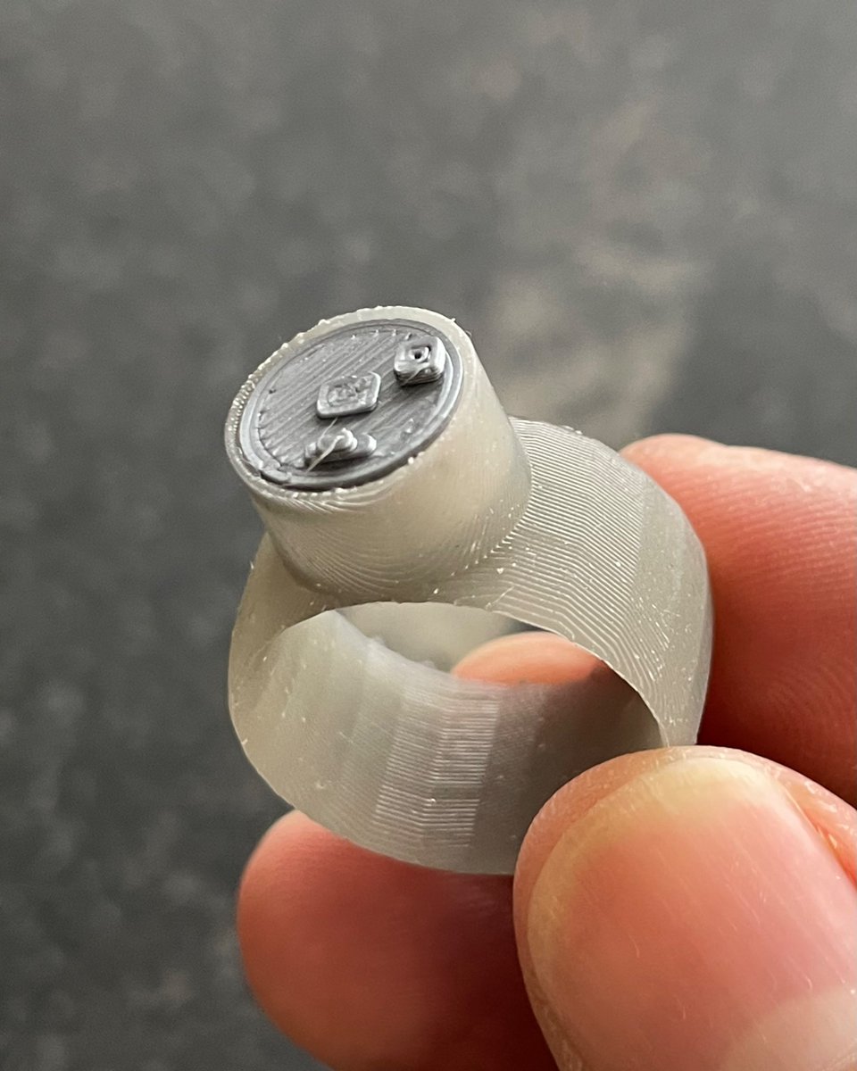
(original)
Replying to @wm_j_kennedy
This is just driving from MCU outputs, so it’s 10 mA per channel (20mA on the white LED). Aiming to put this in the jewel of a ring, so there’s no sense adding a MOSFET to drive more current; you wouldn’t want to make it so bright that it causes burns!
(original)
Replying to @MarkAtMicrochip and @oshpark
Thanks! Yea I noticed on the site that I’d been able to order small quantities of the L22 in QFN and QFP. I was wondering what made this part different, but this makes sense! Hey @digikey, wanna split a reel of ATSAMD10D14A-UUT? I’d be in for 25!
(original)
the hair keeps the score

(original)
Replying to @real1horn and @TLAlexander
it’s definitely an idea!
(original)
Replying to @illie313
I actually have one of the DA14531 modules on my bench! I’m looking at using it for a possible Bluetooth LE add-on board for Sensor Watch, my main project these days: https://www.crowdsupply.com/oddly-specific-objects/sensor-watch
(original)
Replying to @josecastillo
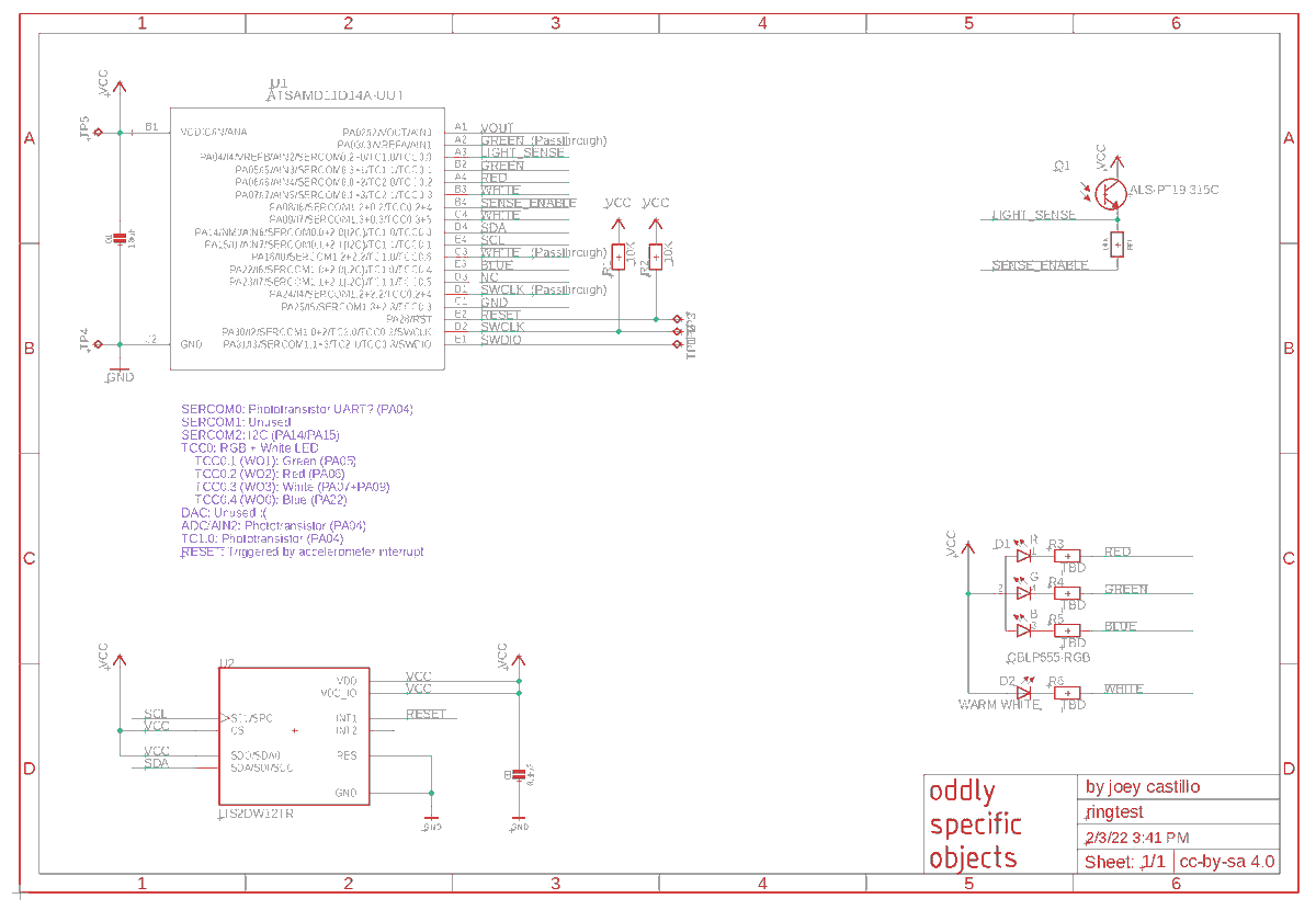
wow this thread got some attention! Here’s the schematic; my notes in purple. lately i try not to share design files til I’ve tested a thing and feel convinced it’ll work. but screw it, this one’s just for fun; i haven’t even assigned it an identifier yet: https://wetransfer.com/downloads/781a657b8afa3c7bfc2fc8c9825d4a7420220203205059/9fa805
(original)
Replying to @RWB93174525 and @oshpark
promising! This is also 0.4mm spacing
(original)
Replying to @josecastillo
the one bummer is the D10 has no OFF mode, so the lowest current consumption we can get is ~9µA. Which means it’ll only last a few months in standby. Still, a necessary tradeoff to make use of the D10’s tiny 20-ball WLCSP package (the low-power L21 only comes in a 64-ball WLCSP).
(original)
Replying to @josecastillo
this ring would not be for gathering data; more a fun toy or prop. I imagine the accelerometer interrupt triggering a reset, and then code checking for the reason and sensing for a bit. Double tap for a flashlight; do a fist pump to light up a motion-responsive color swirl. Fun!
(original)
Replying to @josecastillo
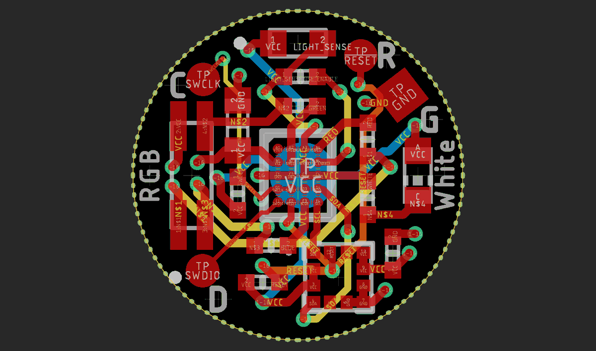
Intent is for it to validate against @oshpark’s 6-layer design rules; the only thing that isn’t 💯 is the spacing of the WLCSP pads, but I sense I can get away with it. Bigger challenge is that the SAM D10 it uses is unobtanium in small quantities right now, but one can daydream!
(original)
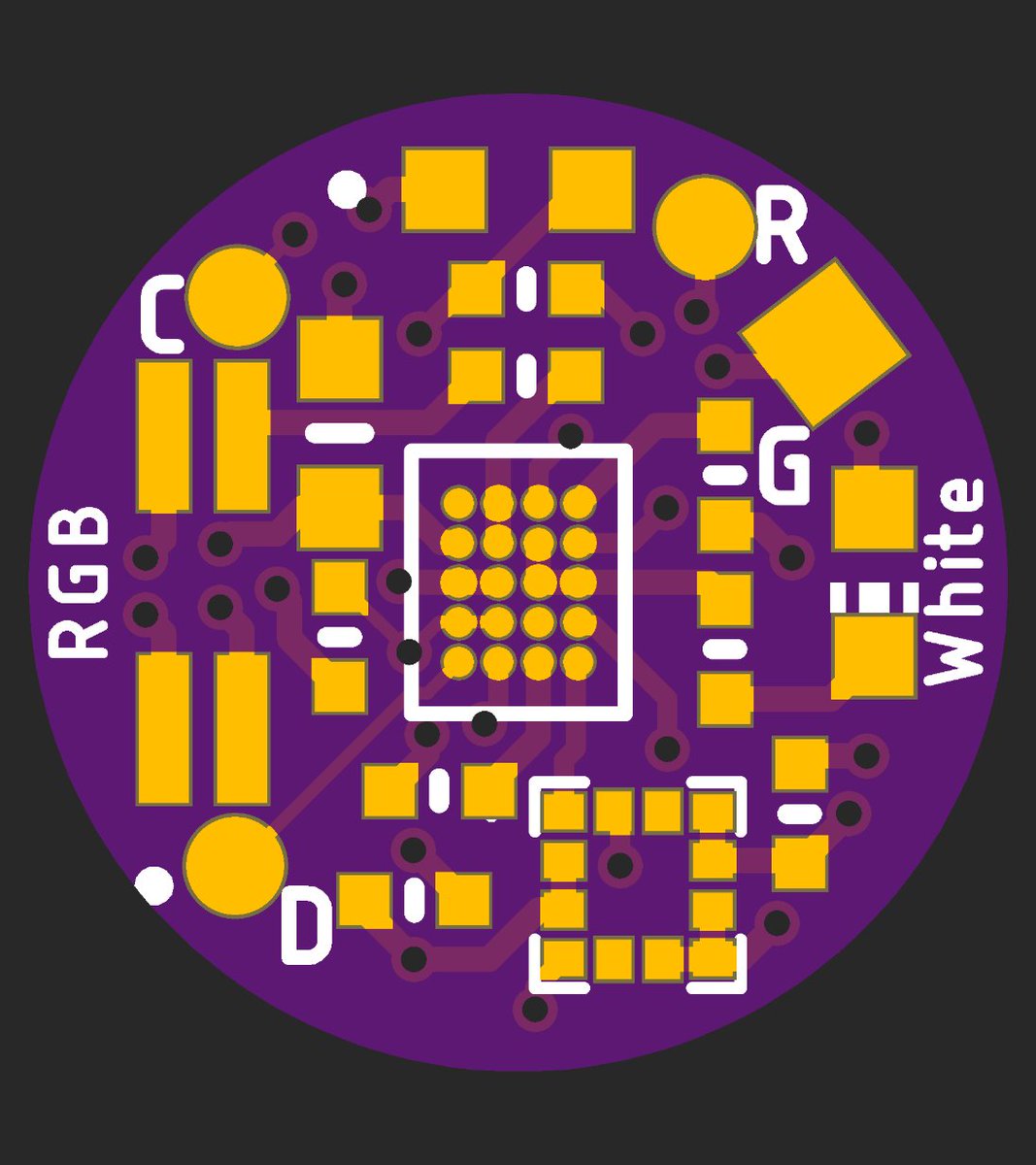
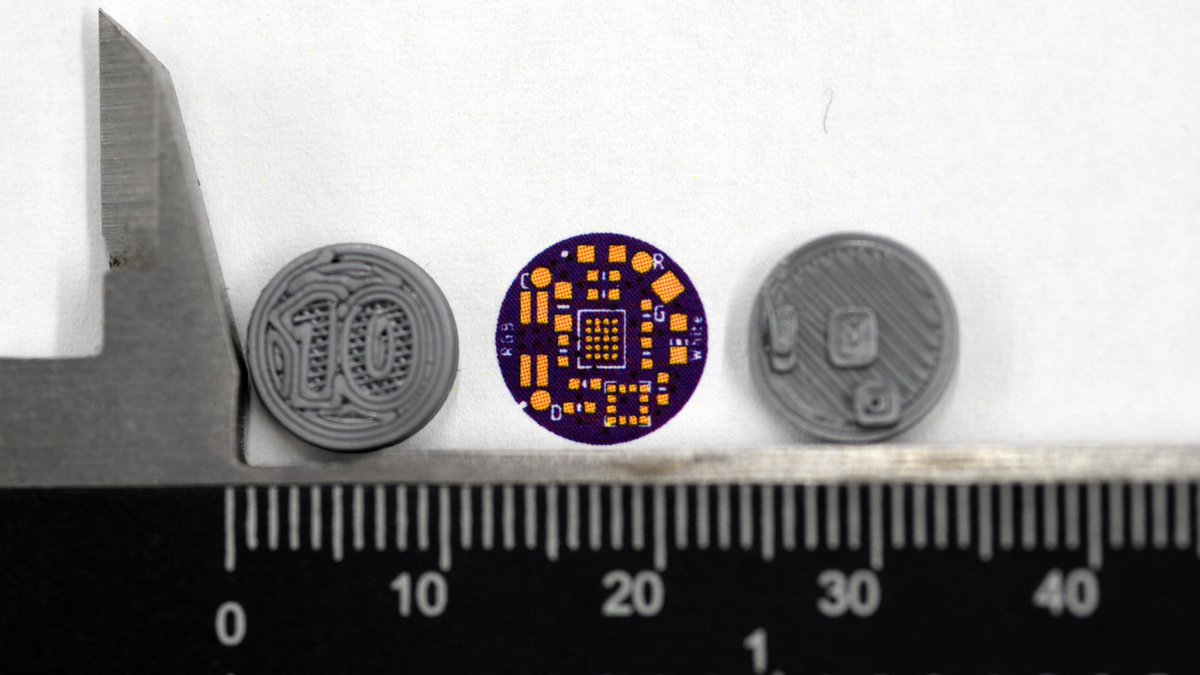
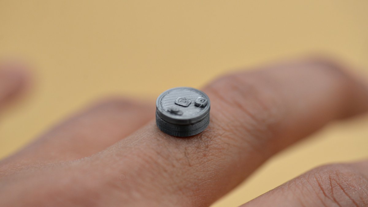
today I laid out, without question, the most absurdly tiny gadget I have ever considered. I even 3D printed it to marvel at its smallness. Designed to sit atop a 10mm coin cell, it manages to fit in an ARM microcontroller, accelerometer and light sensor, plus RGB and white LED’s.
(original)
RT @Alan_Taylor_314: I heard from @josecastillo that wristwatch quartz crystals were shaped like tuning forks. That seemed so weird!
But w…
(original)
I am MONUMENTALLY STOKED to share this week’s #SensorWatch update! It’s a BEAST: clocking in at a cool 3100 words, it takes you on a grand tour of the circuit board, describing every last component and how each one contributes to the workings of the watch: https://www.crowdsupply.com/oddly-specific-objects/sensor-watch/updates/how-we-got-to-blinky-a-tour-of-our-circuit-board
(original)
Replying to @DHammarskjold
LMAO, let’s do HDMI next!
(original)
Replying to @femtoduino
[butterfly meme] “is this skeuomorphism?”
(original)
Replying to @arturo182
Just name it “Untitled”. Eventually some long-suffering curator will be forced to rename it “Untitled (47 circuits on fiberglass)”.
(original)
Replying to @josecastillo
Is there a good water metaphor for an inductor? Capacitors are little water tanks, resistors are kinks in a hose. Diodes are flow valves. Is there anything in plumbing that does what an inductor does, or is this just a taunting reminder that electricity doesn’t behave like water?
(original)
Replying to @josecastillo
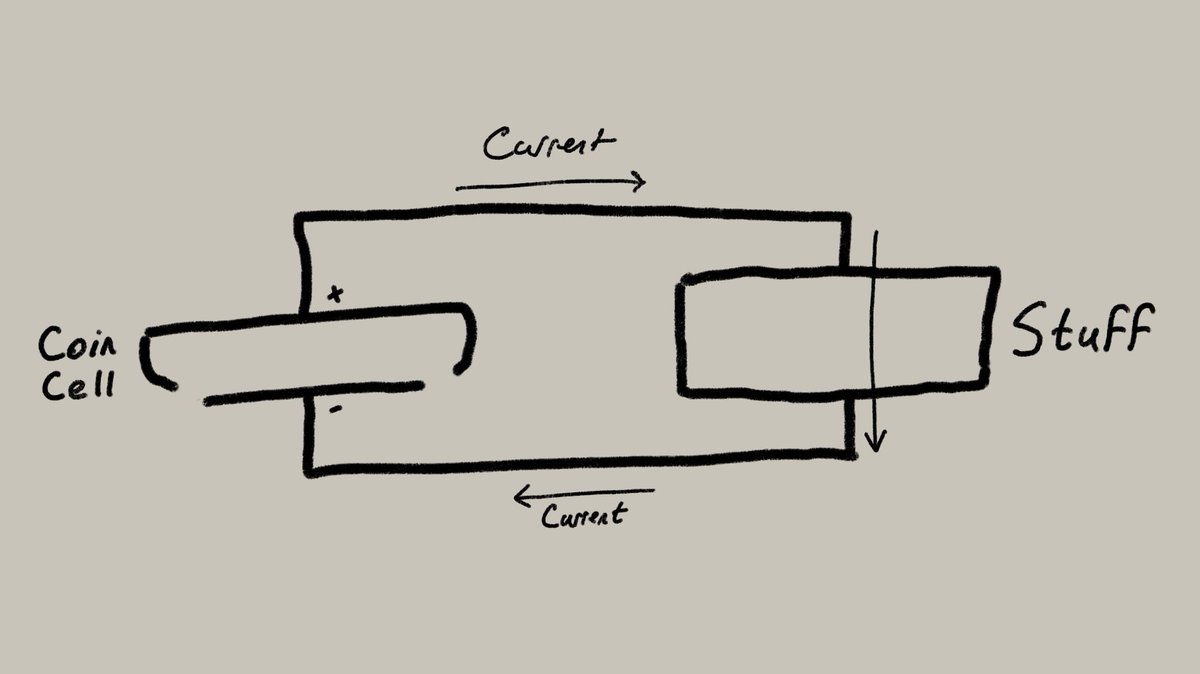
(I am, on the other hand, abundantly certain that this is the best schematic diagram I’ve ever drawn.)
(original)
Replying to @josecastillo
Come roast me! Is it possible I’ve made it this far without actually understanding how electronics work? But seriously, I’m actually a bit uncertain whether the water metaphors are good, and if I’m correctly explaining what the load caps do to the crystal: https://github.com/joeycastillo/Sensor-Watch-Documentation/blob/temp-for-review/temp/update.md#x1-c7-and-c8-the-quartz-crystal
(original)
Want a preview of tomorrow’s #SensorWatch backer update today? I’m soliciting feedback on the post! It involves a lot of explaining how electronics work, and while I know a bit, I also don’t want my tortured metaphors / misunderstandings to mislead people. https://github.com/joeycastillo/Sensor-Watch-Documentation/blob/temp-for-review/temp/update.md
(original)
Replying to @josecastillo
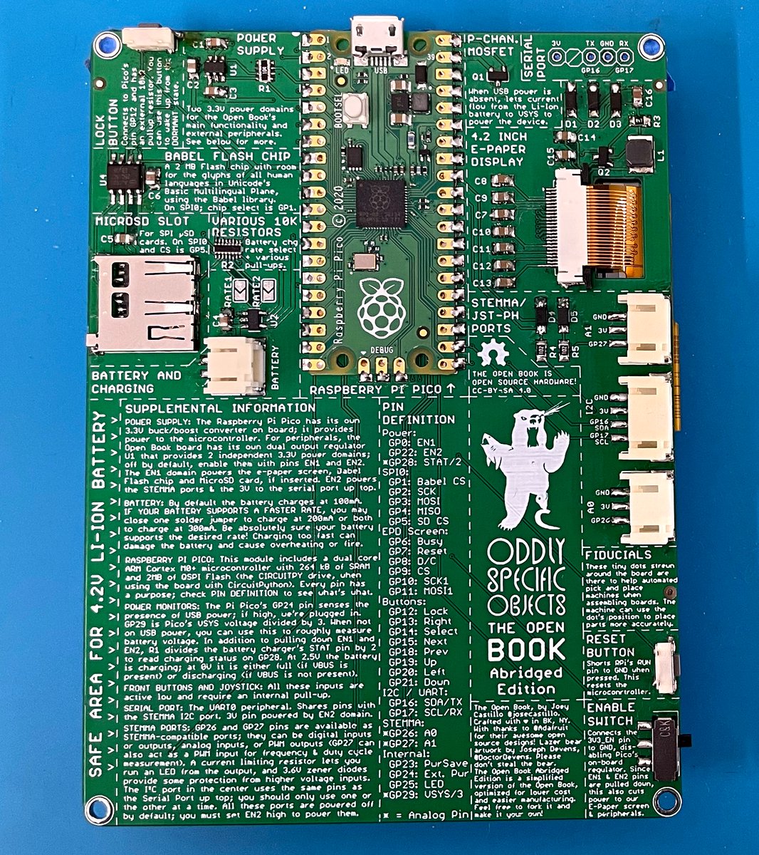
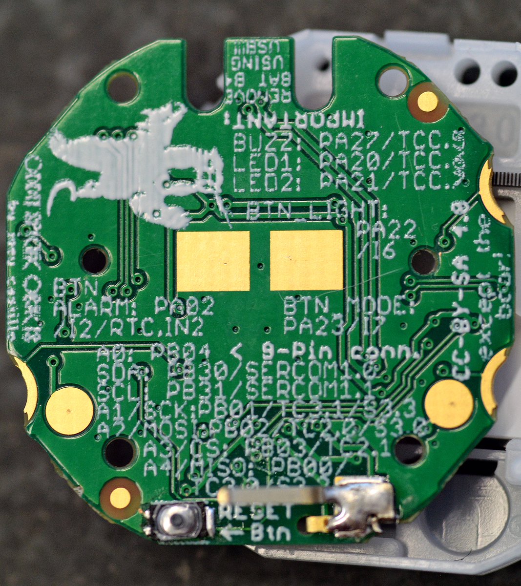
side note: it’s no Open Book, but still I’m proud of how much Good Information we’re able to squeeze onto the back of Sensor Watch’s 24.5 mm diameter PCB.
(original)
Replying to @josecastillo
related:
☑️ photos for blog post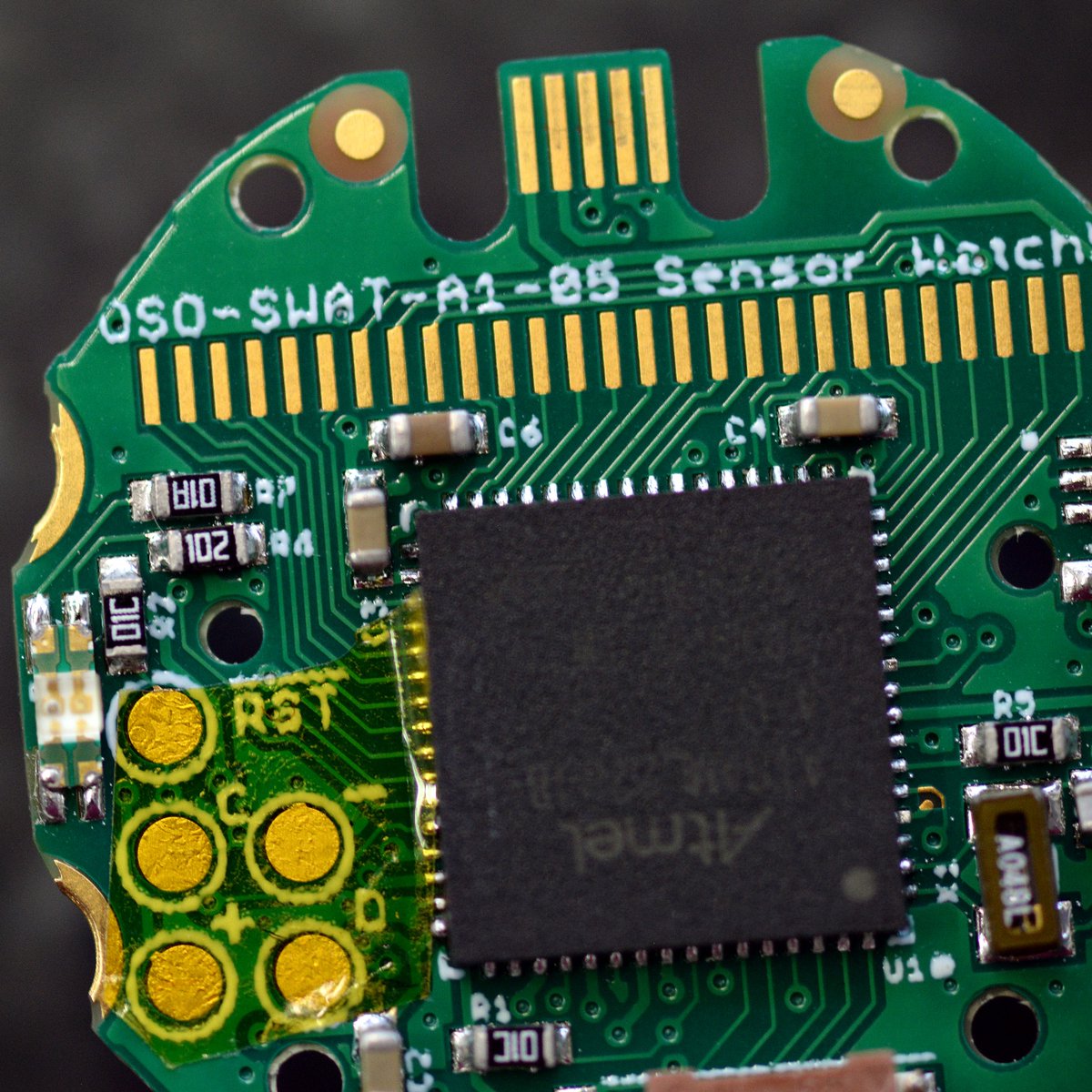
(original)
every time I think about tweeting about my todo list, I do something on my todo list instead. this is good because the things get done.
(original)
It’s 5:00 PM on the east coast and that means that I am CHECKED OUT for a much needed break. Offline through Tuesday; I’m not even bringing a laptop where I’m headed. Joey out!!
(original)
Replying to @josecastillo
Also it goes without saying, it would be SO RAD to do a mod that reuses the solar panel in the bezel. With a smaller battery it would have to sip power just as much if not more than the Sensor Watch (BACKUP mode would be essential!) but wow, what a watch for the end of the world.
(original)
Replying to @josecastillo
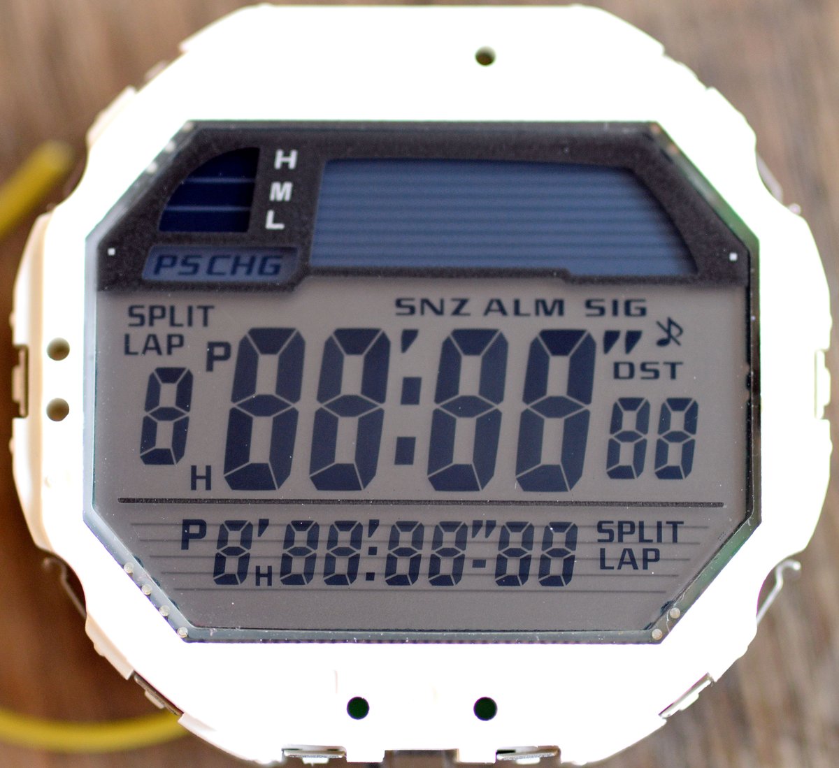
The one frustrating bit is the dot matrix at the top would be inaccessible, but with a second SAM L22 J, you could probably drive that as well (31 LCD pads). Silly to have two ARM MCU’s on one board? Absolutely. Cool? Maybe! ¯\_(ツ)_/¯ https://twitter.com/josecastillo/status/1463663567882829828
(original)
Replying to @josecastillo
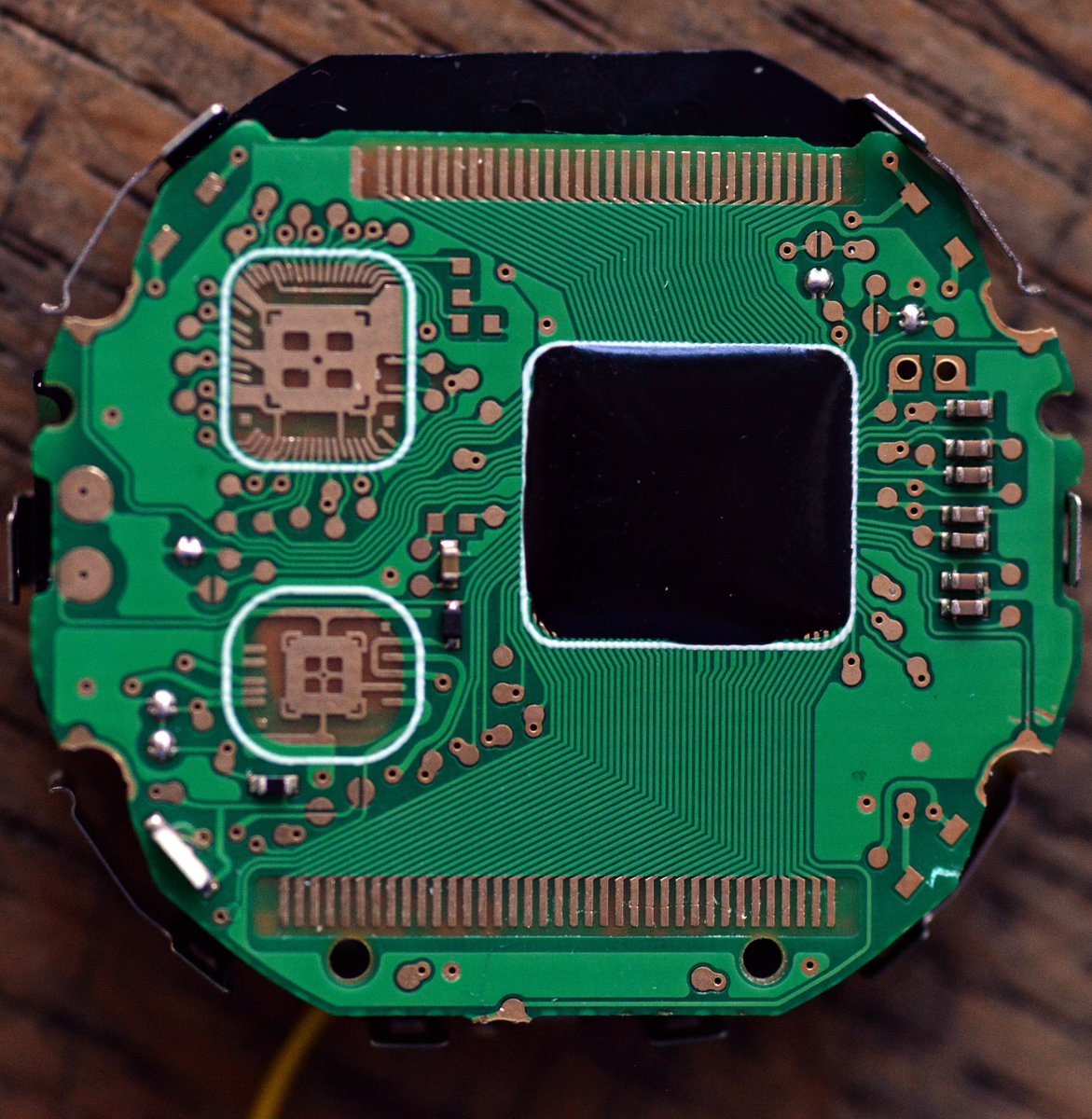
You could repurpose like 90% of the Sensor Watch firmware to drive the LCD and the peripherals (it uses a SAM L22 J), and all the SERCOMs and peripherals would be familiar. I bet you could even stuff SW’s top row of text into the bottom row to make watch faces sort of compatible.
(original)
I have too much on my plate with Sensor Watch, but if anyone’s looking for a watch mod to make their own: consider hacking on the Casio Tough Solar. All these segments are drivable using the 37 pins on the bottom, I believe with a 3V VLCD. Possible with a SAM L22 N, I think! 1/2
(original)
Replying to @josecastillo
bonus content, since alas we couldn’t get to animate inline: 03‑terrible‑bike‑light.gif
(original)
Sensor Watch: Week Three! In which we code a new watch face from scratch in the space of 1,000 words. Minor spoilers: it blinks.
Also: an update on @davidskeck’s new watch face generation script, and another about @a2’s Sensor Watch Emulator. Jam packed! https://www.crowdsupply.com/oddly-specific-objects/sensor-watch/updates/week-three-coding-a-new-watch-face-and-another-bike-ride(original)
Replying to @bradanlane
ah yeah this is definitely a naive implementation that will wear the flash unevenly. log a few hundred events, erase, repeat. not necessarily a long term solution, just something that can get me logging data in the short term.
(original)
Replying to @getur
This is great, thanks for the link!
(original)
Replying to @bradanlane
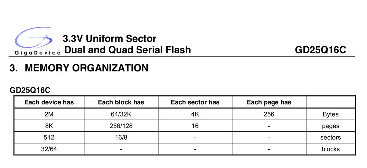
are writes at the page level? I seem to be able to write one byte at a time wherever I want (tho of course, I can’t rewrite any bits that I set to 0 without erasing a whole sector)
(original)
Replying to @josecastillo
2 was lucky. Then again, 1 was very unlucky. Wordle 222 3/6*
⬛⬛⬛⬛⬛
⬛🟩🟩🟩🟩
🟩🟩🟩🟩🟩(original)
Revisiting! So I have a working Flash chip now, but I’m lazy and I feel like it would be a lot of work to implement a filesystem. New thinking: 10 bytes × 25 Hz × 15 sec = 3750 bytes. I could just fill up the Flash chip sector by sector and store 511 events! Which is plenty, tbh. https://twitter.com/josecastillo/status/1480693397870592000
(original)
Replying to @josecastillo
Power of open source: I was racking my brain, surely someone’s written C code for interfacing with SPI Flash chips like this. Then I remembered: CircuitPython is C! So I borrowed their MIT-licensed code. With minimal changes, I had it working in an hour :) https://github.com/joeycastillo/Sensor-Watch/blob/main/watch-library/shared/driver/spiflash.c
(original)
Replying to @josecastillo
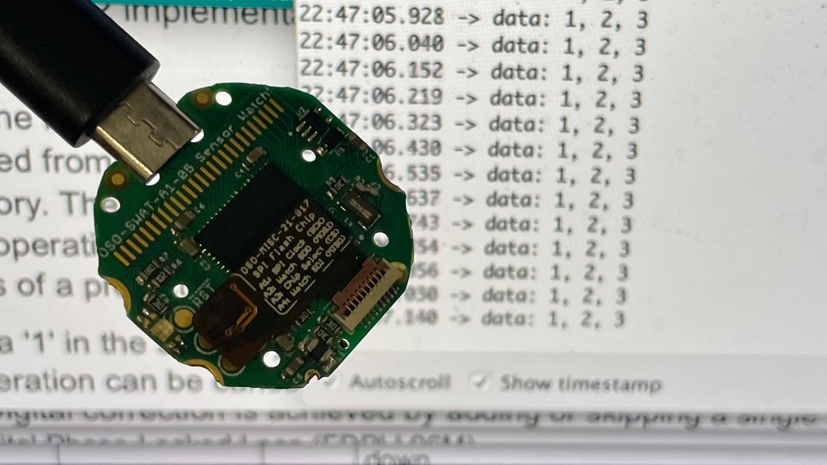
It may not look like much now, but this is me writing values to the first three bytes of the 2MB Flash chip, and reading them back out. From here to working file system is going to be some work, but this was the necessary first step.
(original)
staggeringly productive evening. Finally implemented a proper UART for watch, so we can talk to it via serial. Figured I was already in SERCOMland, so I also implemented our SPI controller. Then (with an assist from #circuitpython!) I got SPI Flash working:https://github.com/joeycastillo/Sensor-Watch/commit/523a5d2f0b3f0d79b16784470870935313dd5775
(original)
oh no. google’s moved ITA Matrix to a new URL (“oldmatrix”) and I hope they’re not thinking of sunsetting it, because I don’t know how to search for flights any other way. https://oldmatrix.itasoftware.com

(original)
Replying to @rohansingh
YES!!
(original)