Tweets
Replying to @dothebart and @crowd_supply
They are connected! The button pushers move a little piece of metal that makes contact with the three plated pads at the edge of the board. You do have to open the watch case to hit the reset button, but that is by design :)
(original)
Replying to @cabe_bedlam
Ah dang, I am afraid it might not fit then… the Casio Iluminator watches have some different geometry inside. It really is only tested to work with the official F-91W. (also, I’ve tried it with some clones, and the clones don’t work; the LCD has to be from a genuine Casio)
(original)
Replying to @GeekMomProjects
Fashion is such a huge part of why people wear watches! It’s definitely one of the reasons I picked this one as a base: it’s inexpensive and accessible, but the decades of different styles mean it’s something that can feel at home on anyone’s wrist :)
(original)
Replying to @cabe_bedlam
Curious: does it have a blue electroluminescent backlight that lights the whole screen, or does it have it a dim green (maybe orange?) LED that mostly hits the left side of the display?
(original)
Replying to @josecastillo
*shopmates; we’re not pirates. and this is not the first time autocorrect has done this.
(original)
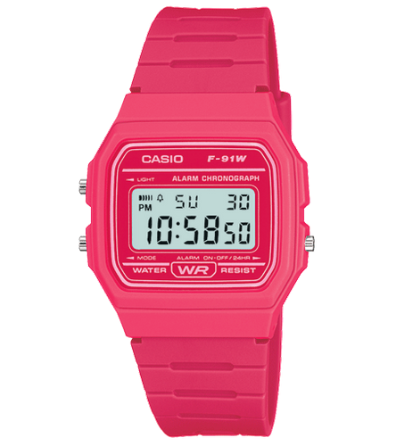
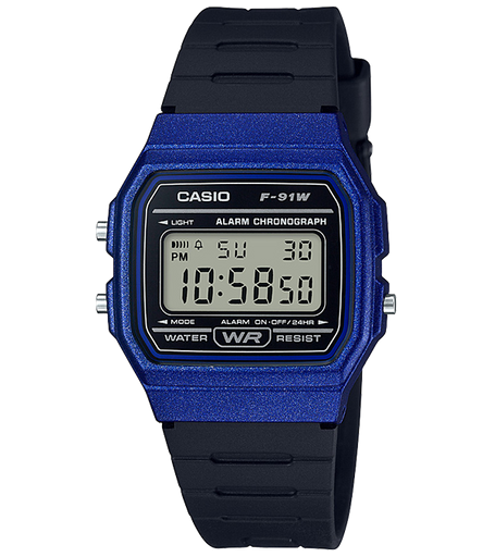
IT’S TRUE! Last night one of my shipmates sent me this one, which comes in a shade of pink I can only describe as Watermelon: https://www.casio.com/products/archive/watches/classic/f91wc-4a (tho I’m also quite partial to Sparkly Blue) https://www.casio.com/products/watches/classic/f91wm-2a https://twitter.com/GeekMomProjects/status/1480936203142635524
(original)
Replying to @RealGene, @spencerbyw and @crowd_supply
This is another reason for the temperature sensor, if one I haven’t talked about much: the SAM L22’s RTC has a frequency correction function. Having temperature available should help us compensate for thermal effects on the 32 KHz crystal oscillator for more accurate timekeeping.
(original)
Replying to @Computeum
Alas, I have not cracked that nut. I’ve tested a front-facing phototransistor for light sensing, and I think I could use that to get data in? But I had to pause that effort just to focus on finishing the main board for the campaign. Definitely foresee future sensor boards tho!
(original)
Replying to @tahnok
has been prolific in writing watch faces for Sensor Watch! He’s been beta testing an early prototype and built the Beat Time functionality, the TOTP watch face, a stopwatch and (soon to be merged!) a countdown timer. Grateful for his contributions! https://twitter.com/tahnok/status/1480732501169643525
(original)
Replying to @Computeum
Casio still manufactures them! One source estimates they still sell about 3 million each year. https://www.casio.com/products/watches/classic/f91w-1
(original)
Replying to @spencerbyw and @crowd_supply
It’s definitely not good for ambient temperatures while worn; your body heat interferes too much. I find the temperature sensor most useful off-wrist using the Temperature Log feature. I like to take it camping and toss it on the ground outside my tent to see overnight low temps.
(original)
One year ago today I shared a brainstorm of an idea, a slim board swap that could add serious smarts and sensors to a classic Casio wristwatch. TONIGHT, I’m thrilled to share that you can back Sensor Watch on @crowd_supply and get one of your own!! 🎉 https://www.crowdsupply.com/oddly-specific-objects/sensor-watch
(original)
Replying to @josecastillo
napkin math: a motion event is 15 seconds of data logged at, say, 25 Hz.
14 bits × 3 axes = 42 bits ≈ 6 bytes
6 bytes × 25 Hz × 15 seconds = 2.25 kB. Round up to 2.5 with some timestamps/headers.
2 MB ÷ 2.5 kB = 800 pieces of training data I could log on one chip before dumping.(original)
Replying to @josecastillo
to be clear, this is me trying to stuff an entire extra chip into the tiny area occupied by these four test pads. But it would be useful because if I made a UI for recording motion training data — jogging, sleeping, etc — I’d have 2 MB of room to store it. https://twitter.com/josecastillo/status/1479906707551793156
(original)
this is ridiculous. Is this ridiculous? This is ridiculous.

(original)
my first wordle was a 3/6 and I swore I wouldn’t jump on the score posting bandwagon until I got another one. anyway: Wordle 205 3/6
⬛⬛🟩⬛⬛
⬛🟨🟩⬛⬛
🟩🟩🟩🟩🟩(original)
Replying to @josecastillo
…decade-old ramshackle bike through a wet honking cacophony of slick cold streets to a warm burrito that some cities would kill for and never truly know. To be clear: I’m not saying that New York is the greatest American city. I’m just saying: this is where it’s happening. (2/2)
(original)
I love living in New York. I love working on big things in shared space with brilliant colleagues; love wandering to a new bar with strong drinks to talk to a great friend about how to live a good life here at the end of the world. I love making a phone call and piloting my (1/2)
(original)
Replying to @matterpoetry
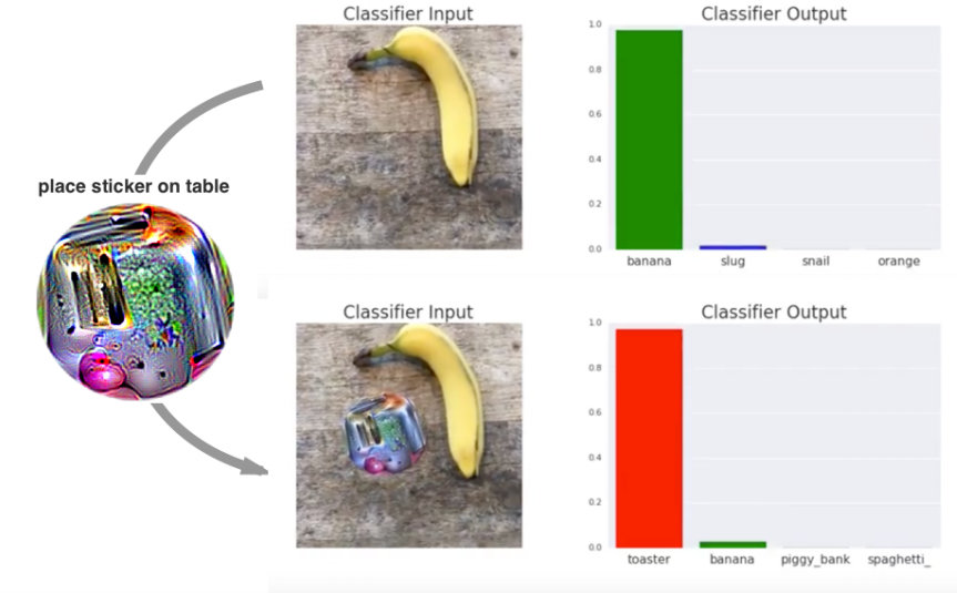
I just want to wear a cyberpunk bandana that says I’m not a threat.
(original)
RT @AlexBlechman: Sci-Fi Author: In my book I invented the Torment Nexus as a cautionary tale
Tech Company: At long last, we have created…
(original)
Replying to @arturo182 and @kicad_pcb
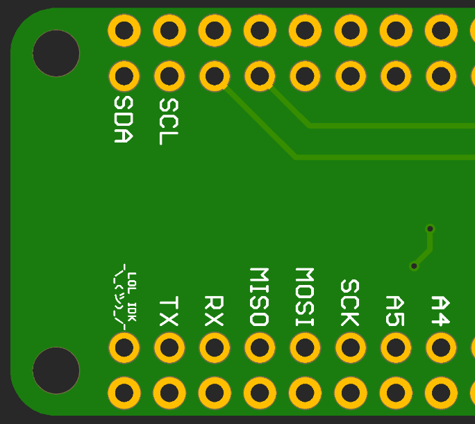
I think this is technically part of the Feather specification…
(original)
Replying to @josecastillo
This was a fun hack because it was the only BLE board I could find in the shop, but it doesn’t break out GPIO pins. So I soldered the GND pin to some ground pads and the TX pin to the LED, since the NRF52840 lets you use any pin as a UART RX. (code is #CircuitPython, naturally)
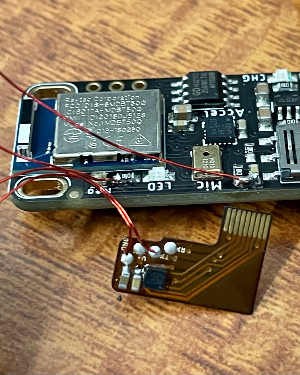
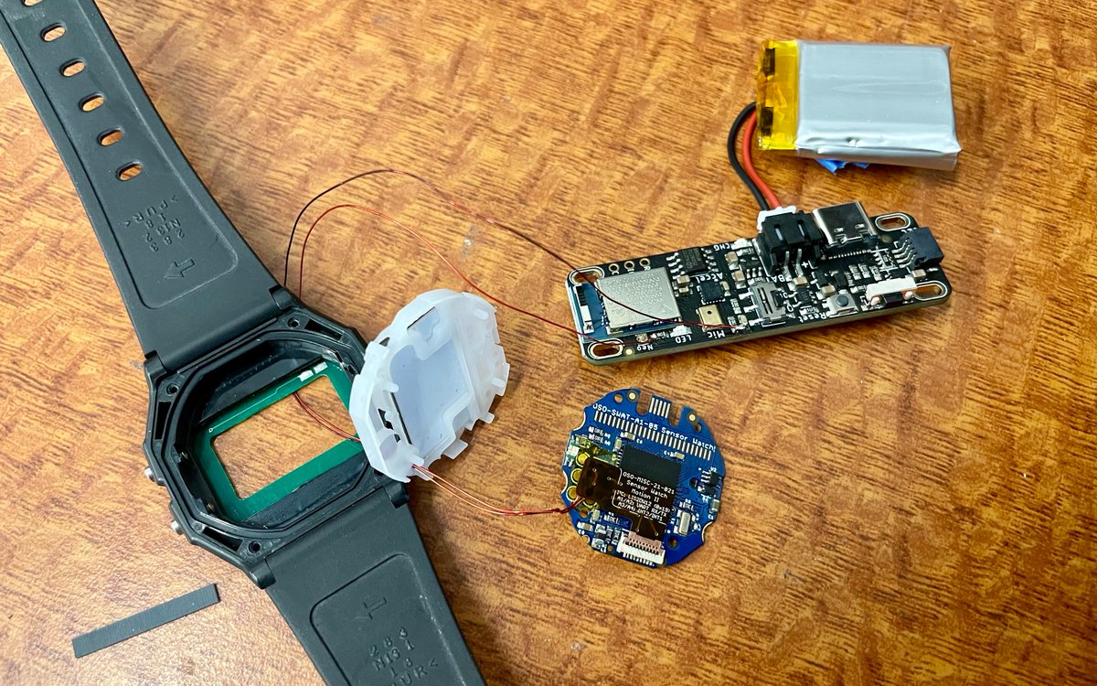
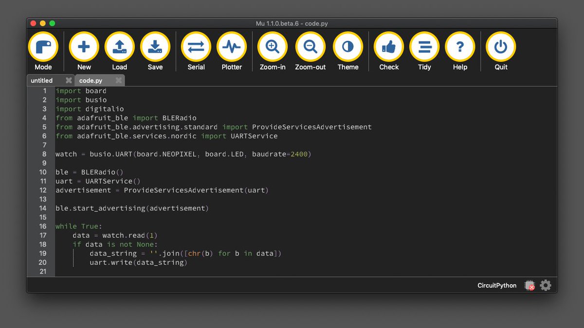
(original)
I’m untethered! Using a spare @adafruit LED Glasses driver to stream realtime accelerometer data from the watch. This is cool bc if I use this to train a machine learning model, it’ll be in situ data: not something like my sensor, but my actual sensor, in a watch case, on an arm.
(original)
Replying to @adafruit and @NordicTweets
I will be first in line for this one!
(original)
Replying to @DHammarskjold
And yea, definitely a hotplate when soldering the LIS2DH. I had success with it once (maybe twice) in an oven with a stencil, but after too much heartbreak I just gave up and went the hot plate route; I’ve have had marginally more success since. Hope this new part is even better.
(original)
Replying to @DHammarskjold
THESE LOOK SO COOL! So much going on in such a small space!
I feel good about lines as thin as 2 mil on OSH Park flex; most of the text here is 14 mil tall and 2 mil lines. any smaller and I’ve had mixed results (like that old accelerometer board above).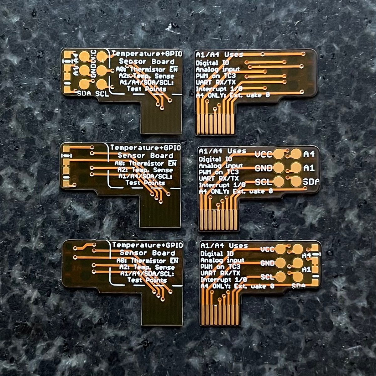
(original)
Replying to @josecastillo
bottom line, I think this board could replace the temperature sensing board to cleanly add three new low power inputs and motion tracking — all without sacrificing accurate temperature sensing (which we’re really going to want — more on this eventually…)
(original)
Replying to @josecastillo
But second: it’s better. Newer, lower current draw (BELOW a µA!), more and more interesting configurable interrupt options (tap, double tap), and a 12-bit temperature sensor, which means it can detect differences of 1/16th of a degree C, where the LIS2DH can only do full degrees.
(original)
Replying to @josecastillo
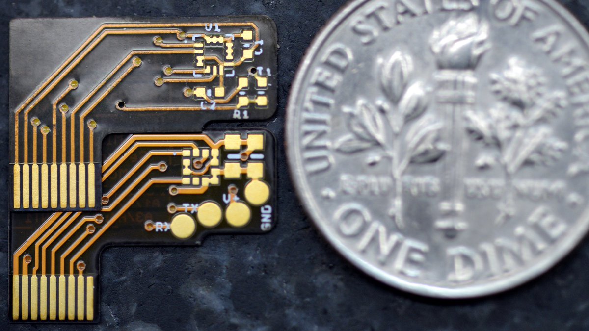
You may be wondering: why a new accelerometer board? Two answers: 1st, the LIS2DH (U1 footprint up top) was legitimately impossible for me to place reliably. Even with a stencil I could barely get paste on the pads. The 12-pin LIS2DW (bottom) should be worlds easier to work with.
(original)
Replying to @josecastillo
in the end it’s yeoman’s work: just implementing register definitions from a data sheet and doing what you’re told. But this is the beginning: from here I can log really good motion data for stuff like activity tracking and machine learning model training. https://github.com/joeycastillo/Sensor-Watch/commit/496530c85c3848c04fcafa912d11b0f1991777c1#diff-a1cb978154cfcefb2557667dbe189f954618bbb8a079e41640194c32ea7eb3c1
(original)
Replying to @josecastillo
trying something without success is the first step on the way to doing it successfully.
(original)
Replying to @femtoduino
lol just my skill level; after a second reflow, it worked fine. I would solve all of this for myself if I just got stencils with these, but I’m stubborn and cheap and always figure “it’s just a [difficult part], how hard could it be?”
(original)
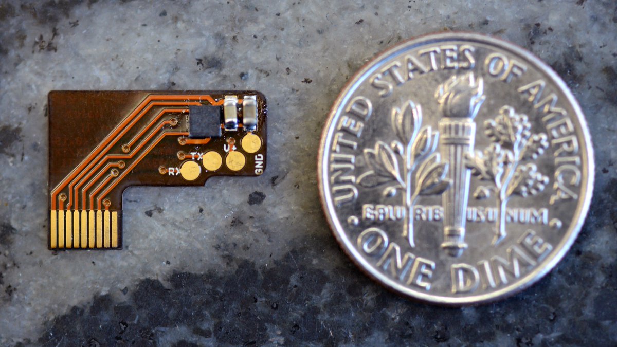
also today: testing — so far unsuccessfully! — the new accelerometer sensor board prototype. It is legit crazymaking how tiny these boards are. Some real “me sowing / me reaping” energy every time I get a new one back.
(original)
Replying to @highenergybeams
heh no software really, just drew some green lines in Photoshop to indicate my thinking. I don’t know the correct way to do panelization if I’m being honest, but I’m sure I can learn.
(original)
Replying to @bradanlane
Looks gorgeous!
(original)
Replying to @josecastillo
Closing thoughts: it’s wild how even after you’ve designed a thing, fabricating it is its own process with its own outcomes. I’m pleased with this one. Anyway more to come soon; I’m planning to work with @PCBWayOfficial again on a small panel of flex PCB’s. Should be interesting!
(original)
Replying to @bradanlane
2mm thick is a chonker! Yea these seem pretty tame to sand down even compared to OSH Park 1.6mm boards. still I imagine once you get your process down it can be quite soothing.
(original)
Replying to @jimmyduong
alternatively, with that kind of volume, I could work with a contract manufacturer and pay someone else to do that work as a part of the process of manufacturing the whole widget. I sense the volume’s not going to be *that* huge, but it would be a good problem to have :)
(original)
Replying to @jimmyduong
Yea, that’s why later in the thread I’m still hoping I can figure out a way to panelize this without mouse bites. But if there’s no other way, 10,000 boards * 10 seconds of sanding ≈ 28 hours of labor? Not exactly a joy, but shipping product would pay for four days of blah work.
(original)
Replying to @jimmyduong
I would plan to do the sanding myself tbh; it’s a part of the manufacturing process. A colleague of mine described visiting his contract manufacturer, and seeing a table with people doing just that: sanding off mouse bites from customers’ boards. Just a thing that has to be done!
(original)
Replying to @josecastillo
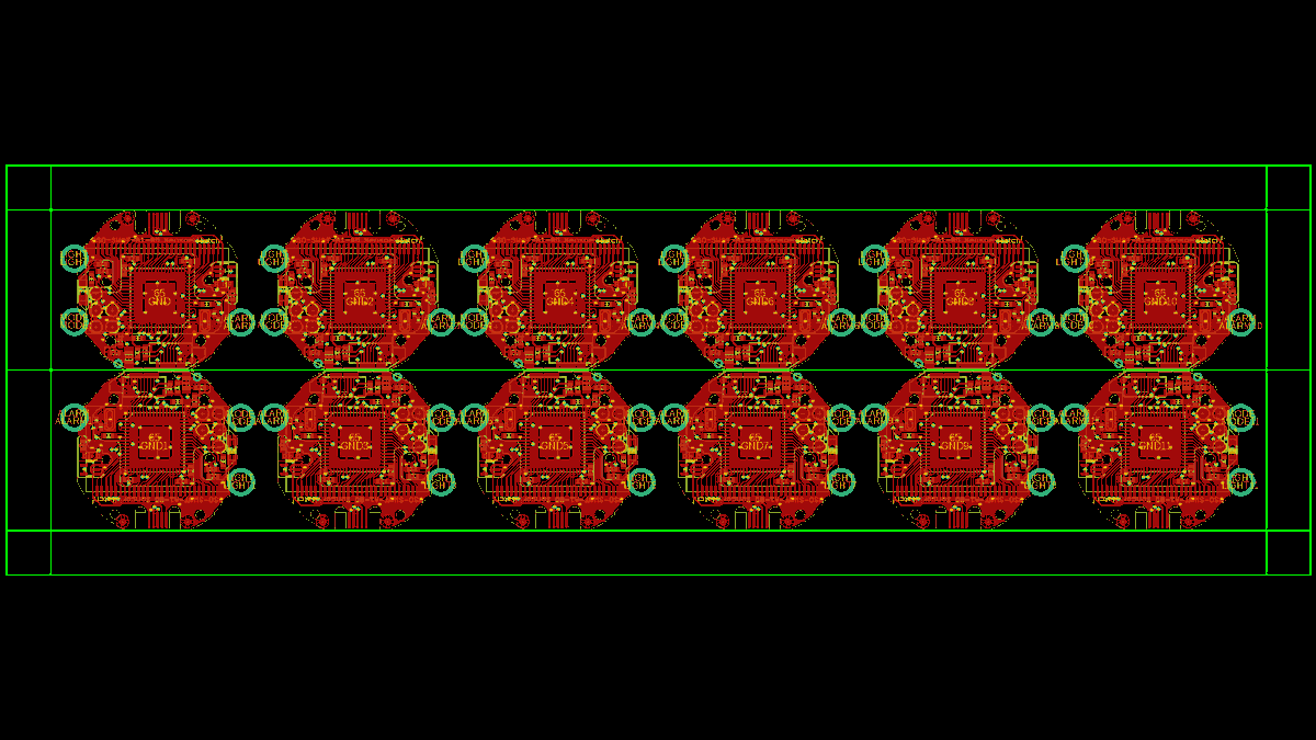
actually glad I did this thread because it forced me to lay it out. Wondering if I could get away flipping one row of boards upside down, so the USB routing all happens on the top and bottom rail; then it could be V-scored (in green) down the middle. I’ll ask about this anyway :)
(original)
Replying to @josecastillo
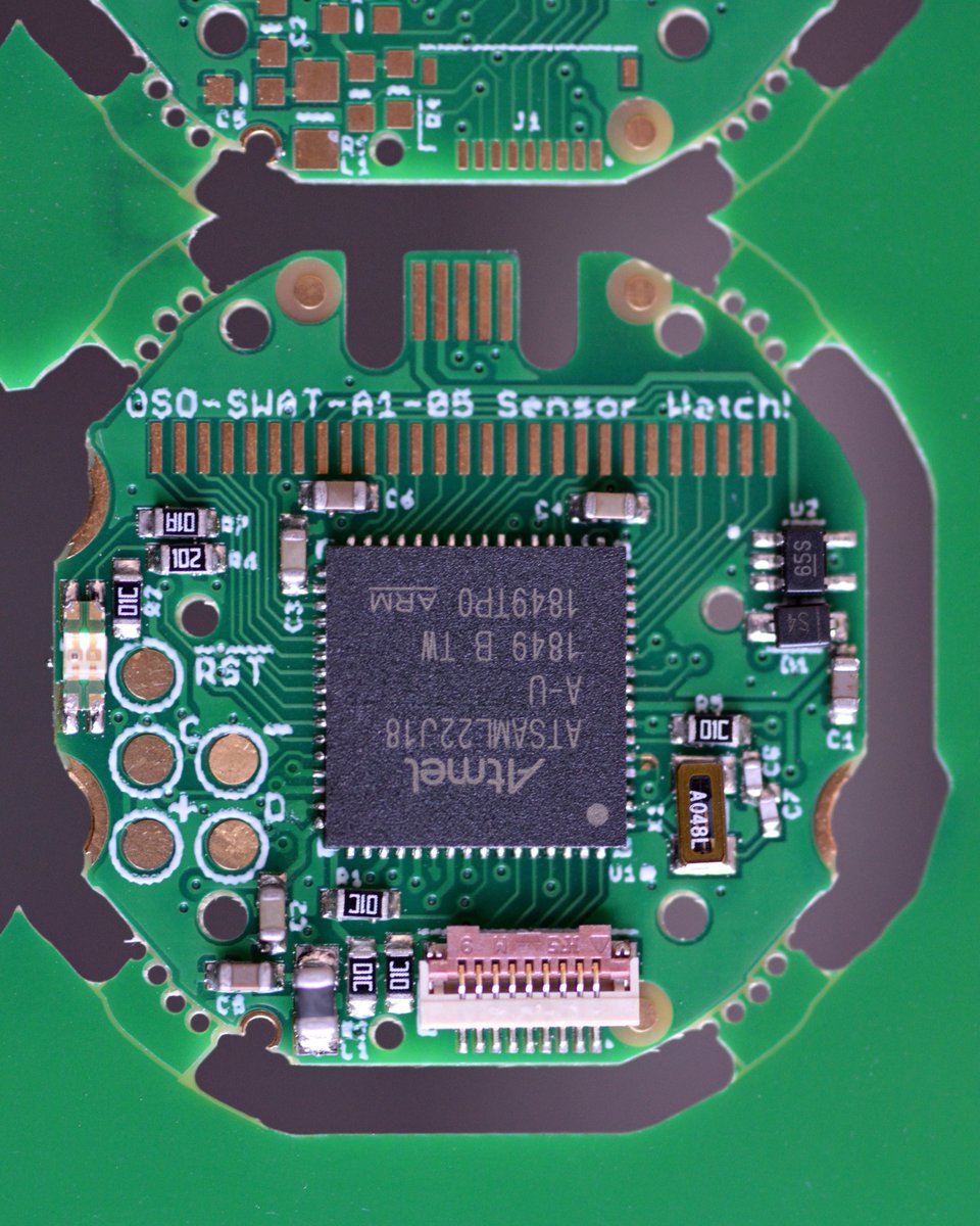
Of course no choice is without tradeoffs, and while this does resolve two major hacks, it also adds one manual step. You saw it at the top: I’ll need to sand off four tabs on each Sensor Watch board I ship. Admittedly not wild about that; as such, I may try one more panel layout.
(original)
Replying to @josecastillo
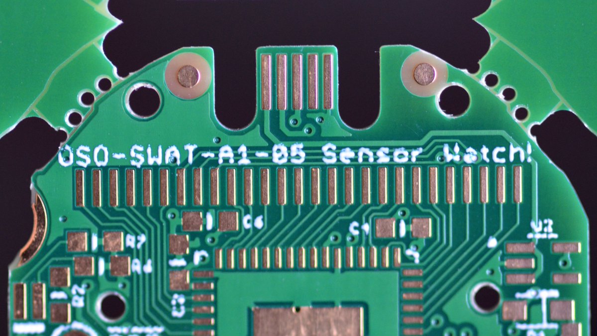
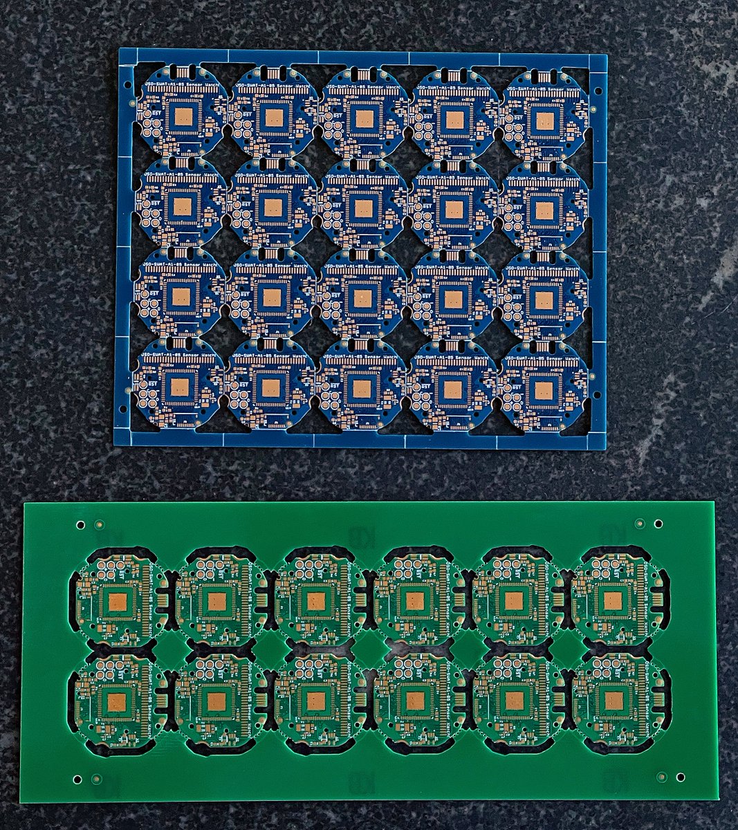
None of these items were dealbreakers, but if I want to scale this up, I need to do it right and minimize the number of hacks & workarounds. @PCBWayOfficial’s engineers suggested using mouse bites, those four little breakaway tabs, to realize this design, and it turned out great!
(original)
Replying to @josecastillo
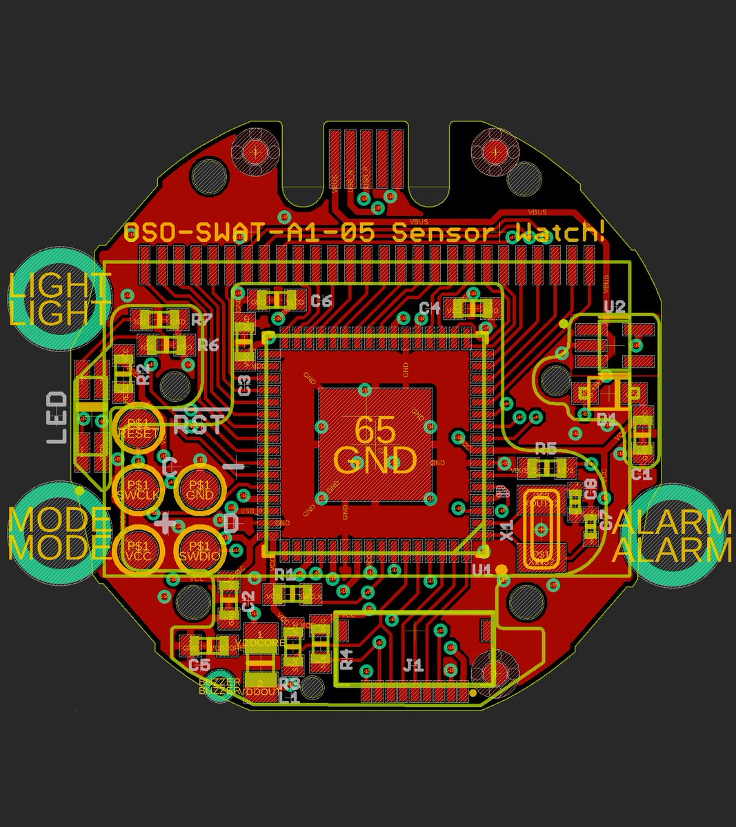
Second: The big round drills became routing paths, which left two artifacts: a smol tab of FR-4 at the top right, and sometimes a whisker of plated copper near the light button. (This would manifest as a test failure if it bridged to R2 nearby!) The new panel fixes both of these.

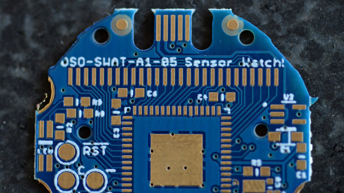
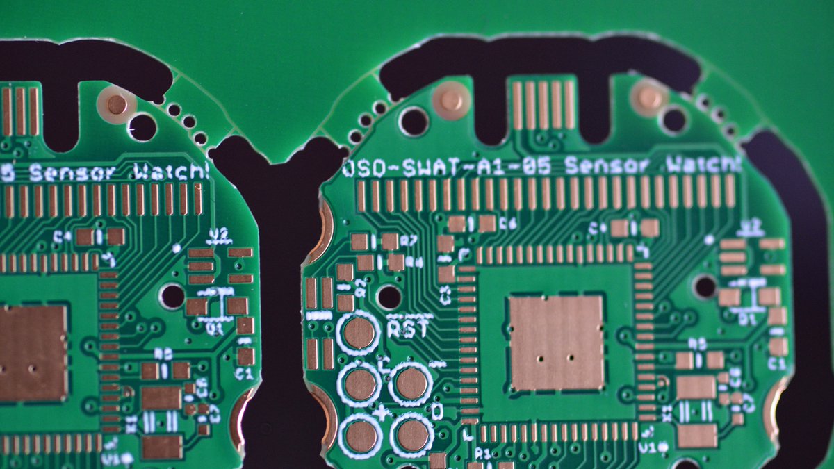
(original)
Replying to @josecastillo
First, the big one: the USB cutout was routed with a big round bit, which meant it wasn’t completely clean. I could use a fingernail to break away the little piece of fiberglass there. But it’s not ideal. The new panel routes all the way around, making for a very clean connector.
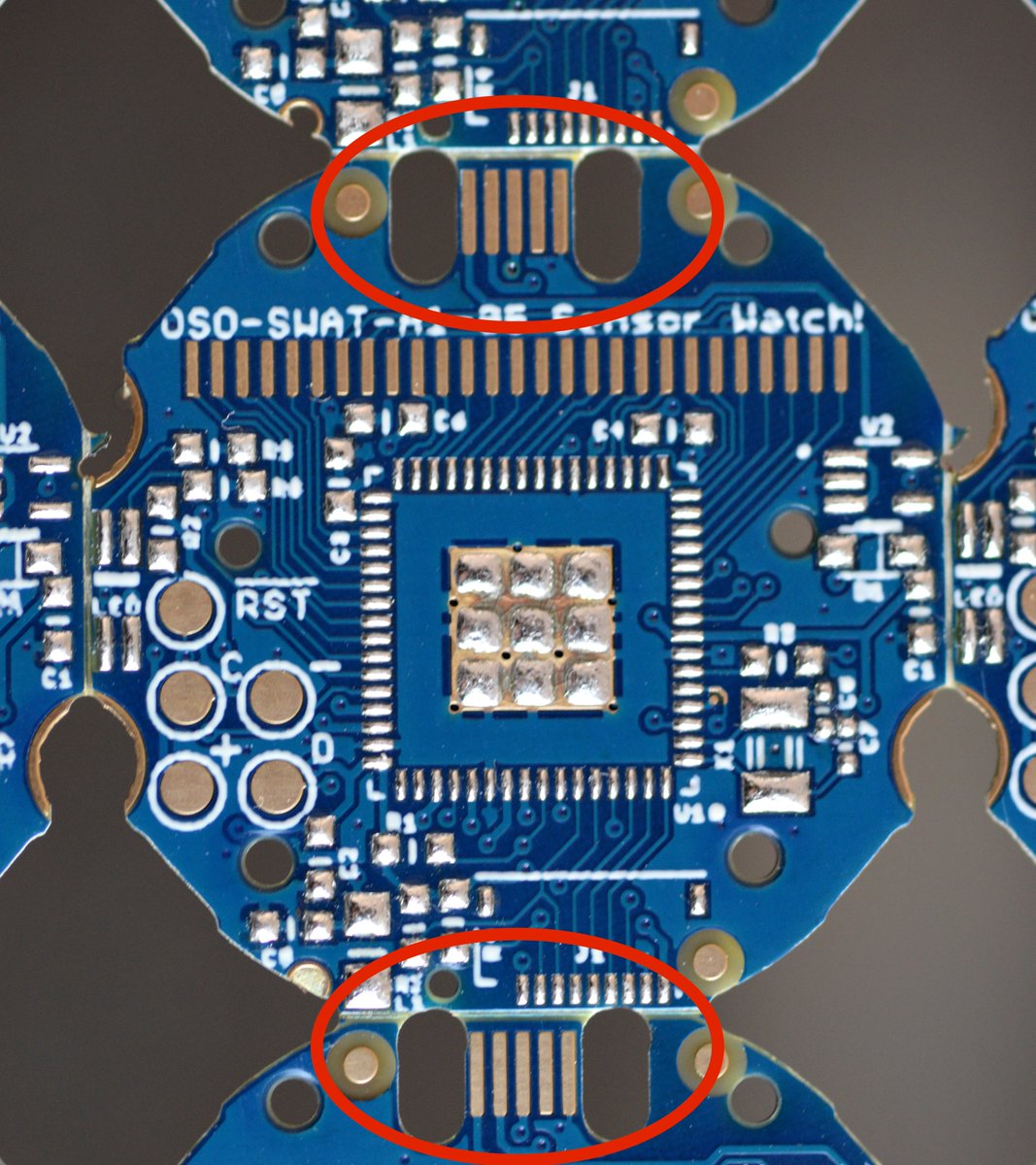
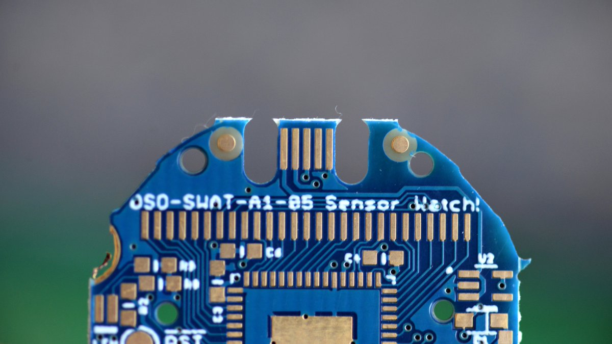
(original)
Replying to @josecastillo
The watch PCB has 2 unique features: three big drills outside the board area to plate the contacts for the buttons, and the USB Micro-B connector which needs to be routed out. The old (blue) panel did some creative things to stay compact and V-scorable. But it led to some issues.
(original)
Replying to @josecastillo
First up: why am I testing a new panel? Don’t I already have a working gadget? The answer is I’ve learned some lessons since the old panel layout, which was done almost a year ago. It did work. Got me to where I am now. But, well, let’s unpack this design. https://twitter.com/josecastillo/status/1371615657364754432
(original)
Let’s get this party started! Depaneling the @PCBWayOfficial sponsored board and playing with it this morning. NOTE: they gave me a discount code for this panel test, but I’m just doing what I usually do here: sharing my process. They haven’t told me what to say at all. A THREAD!
(original)
Replying to @supersat
I would love a watch face that could alert the wearer about visible ISS passes. Combination of orbital parameters and sun calculations, since you can only see it just dark of twilight. But it would be incredibly cool!
(original)
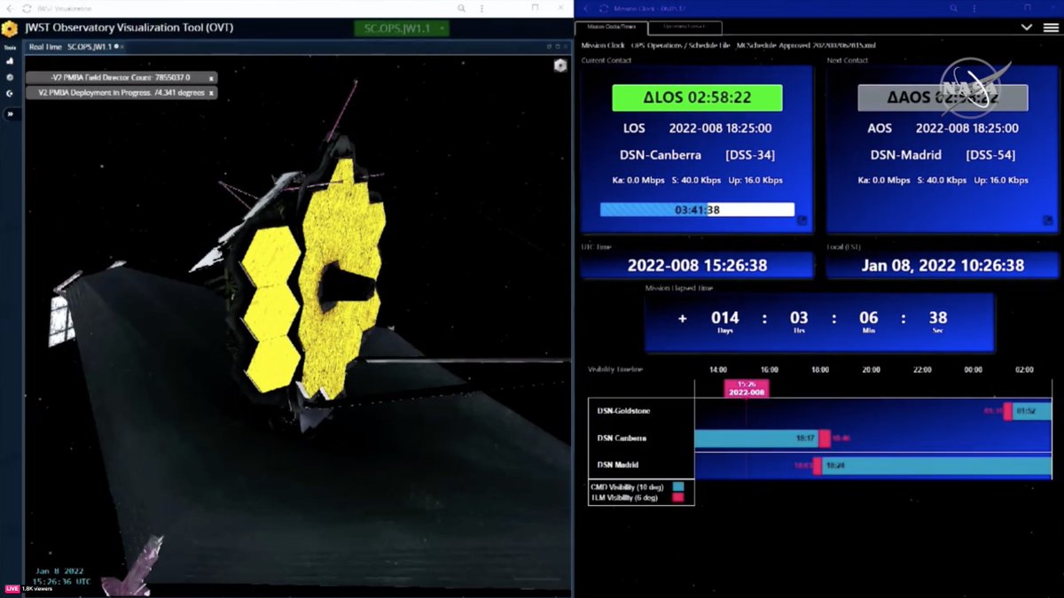
Watching the JWST mirror deploy and loving the mission clock detail on the right. Wondering: if I had the orbital parameters for a space probe, how hard would it be to make a Deep Space Network AOS/LOS countdown for the watch? Is it just when it can see Goldstone/Canberra/Madrid?
(original)