Tweets
Replying to @baldengineer and @oshpark
Reflow oven is my go-to!

(original)
HOLY WOW HOW DID I MISS THIS? @tahnok has created the first third-party app for the watch! It displays Swatch Internet time, aka beat time, which divides the mean solar day into 1000 parts called beats. He’s also open sourced it; his code is here. SO COOL! https://github.com/tahnok/Sensor-Watch/commit/bd4626ab2f1af79674947f793fff01268f459724 https://twitter.com/tahnok/status/1436322833450348544
(original)
huh. I forgot to turn off the Big Board of Death (oops), so it’s been counting deaths by all causes since Jan. 1, 2020. COVID is on track to be the number 4 cause of death for the years 2020-2022. (I was reminded of this when I read that 1 in 500 Americans has now died of COVID.)

(original)
Replying to @sneenyc
the footgun is within you always :)
(original)
Replying to @bitomaxsp
the other big thing is that these are open source designs; I want folks to be able to download and build on them, and it seems like the Eagle / Fusion ecosystem is growing increasingly hostile toward hobbyists. “Better” for my use case means a tool that’s more accessible to all.
(original)
Replying to @bitomaxsp
I’ve paid for it a few months at a time (mostly when I work on the Open Book, which has a board area that doesn’t fit in the free size limitation). The watch is small enough to fit in those limits, but knowing that restrictions and costs are looming, I need to pick a better tool.
(original)
Replying to @bitomaxsp
This is EagleCAD, tho I’m hoping to make the move to to KiCad soon.
(original)
Replying to @josecastillo
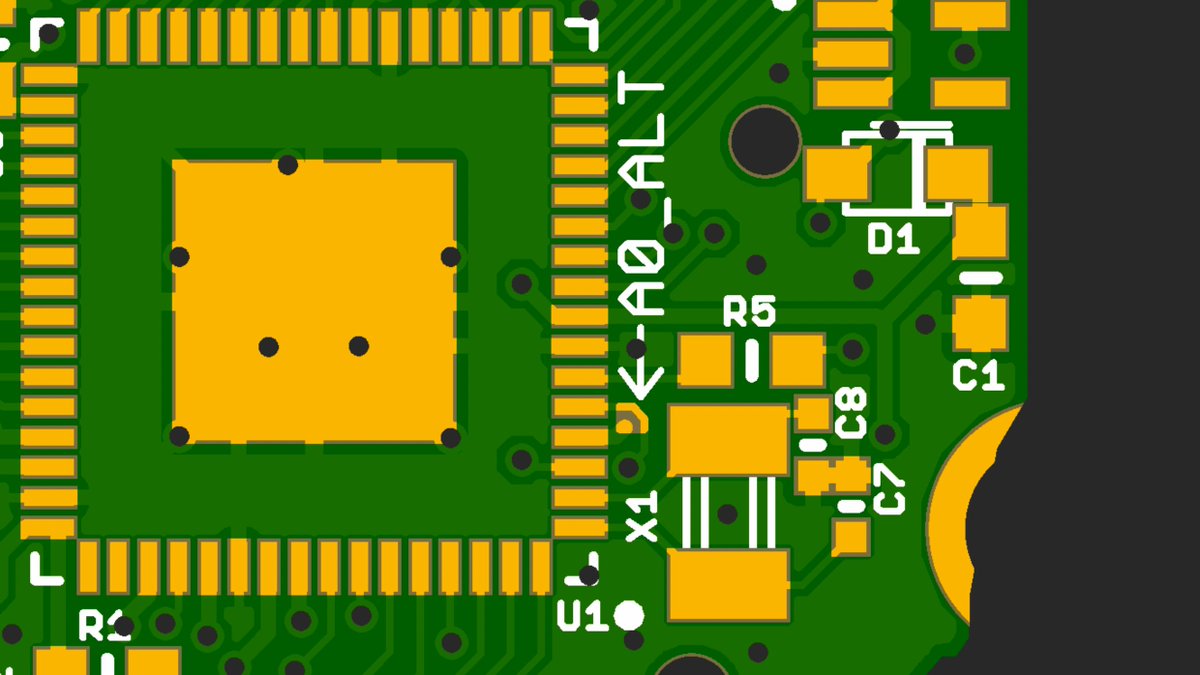
late night idea; may be losing the plot, but leaning toward this now. a teeny tiny solder jumper to connect the second pin to A0’s exposed trace. Disconnected by default to minimize the footgun potential of linking the two pins, but available if your use case really calls for it.
(original)
Replying to @josecastillo
I do see a note on StackOverflow, “using two pins to drive a single source is not uncommon (combining current output)”, so maybe this could be useful to apply a little more oomph to an LED by giving it… *checks data sheet…* three whole milliamperes. https://electronics.stackexchange.com/questions/86331/is-it-safe-to-connect-two-mcu-pins-directly-to-each-other
(original)
unsure if this is cursed. (tying signal A0 to two MCU pins). obviously it’s cursed if I set one high and the other low. but maybe useful to set one as an output, and the other as an analog input? or to only use one or the other, but have the option of two different pin functions?

(original)
this is what I hear when they say “disruptive technology” https://twitter.com/ed_solomon/status/1437605461587529736
(original)
Replying to @CedarGroveMakr
haha, only one way to find out! Tho in this case it’s just a digital output and not a DAC; the SAM L22 doesn’t have a DAC, so my A0 pin doesn’t get any special analog output privileges.
(original)
Replying to @theavalkyrie
OH INTERESTING! It looks like the L22 has the same limitation. Thanks for the heads-up, that does indeed blow a hole in my plan to use it this way. I may still route A0 to the neighboring pin tho; even if I can’t use it as a reference, I could read its value to try to compensate.
(original)
Replying to @josecastillo
the principle is the same and the math checks out, but it’s misleading because what’s happening on the right isn’t actually A0 emitting 3.3 volts. A0 is still slightly below 3.3 volts, but with the correct reference voltage, A1 is measuring the divided value correctly. </nitpick>
(original)
Replying to @josecastillo
reflecting on this after my bike ride and I realize, technically this is misleading… instead of multiplying by 2*3.3, I should have multiplied by 100 to check if the output is 50% of the input. on the left, this would have appeared as just below 50, and on the right, 50 exactly.
(original)
ok but for real, I could get behind this aesthetic https://twitter.com/reillybrennan/status/1437416777693024263
(original)
Replying to @josecastillo
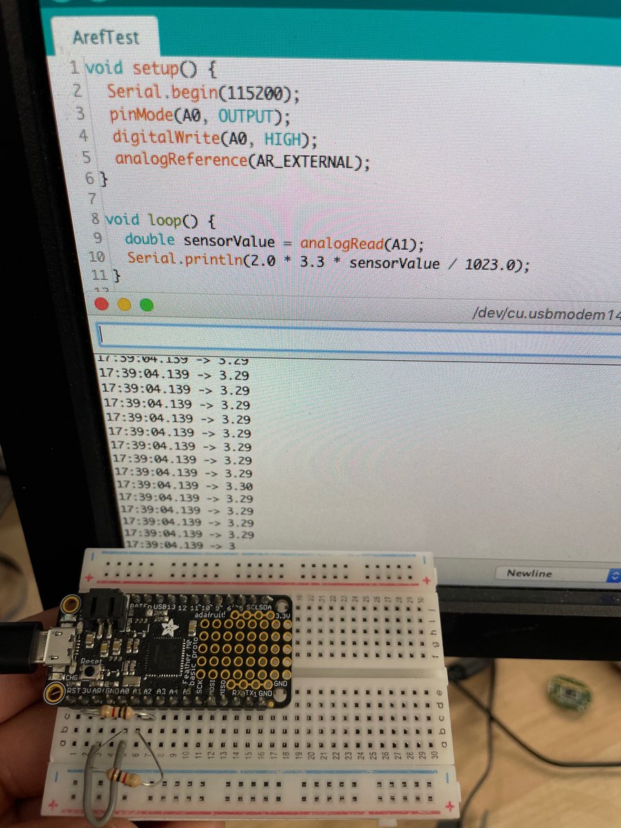
welp. it’s officially worth it. Using two resistors as a voltage divider to measure half of A0’s output on A1. with the standard analog reference it’s 100 mV low. Tying A0’s output to AREF puts it right on the money.
It feels foolish not to make a change when it’s this easy.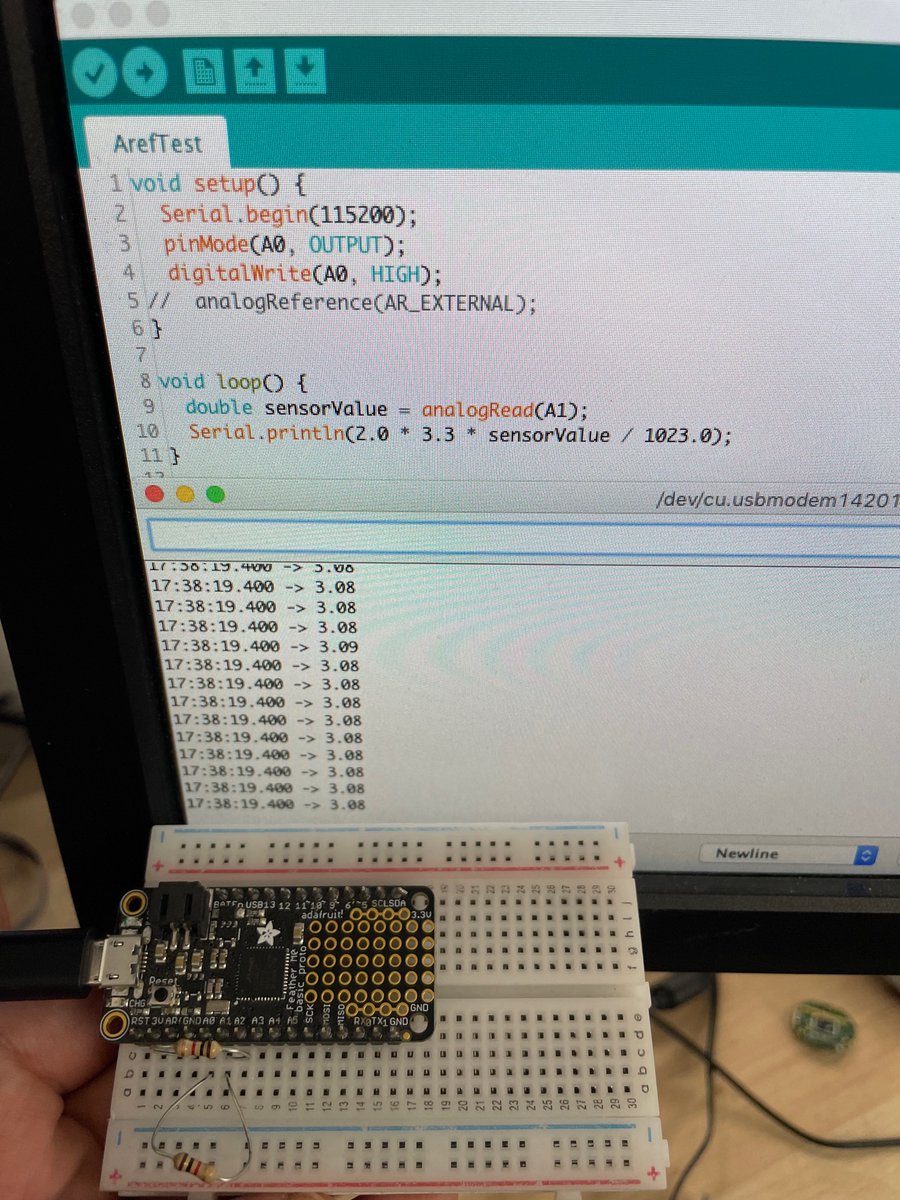
(original)
Replying to @josecastillo
actually come to think of it, this all makes sense in my head, but I should confirm that this actually does what I expect it to do before I launch into it. digging up a Feather M0 to try it out.
(original)
Replying to @josecastillo
I’d still use VDDA as the standard reference voltage; the change would only matter for sensor boards that want to power an analog sensor using A0 as an output. In this case, they could get better accuracy by requesting VREFA as a reference. a bit in the weeds. but maybe worth it.
(original)
Replying to @josecastillo
Ideally I’d like to use A0’s level as a reference voltage — and as it turns out, a VREF pin (4) is right next to A0! I just made the mistake of assigning it to detecting if we’re on USB power. If I move VBUS_DET to pin 6 and tie pin 4 to A0, I can use A0’s output as a VREF input.

(original)
Replying to @josecastillo
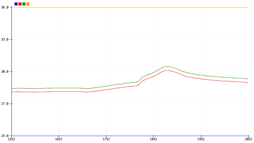
Options: I can assume that when powering an analog circuit from GPIO, I need to adjust the result by 0.7%. Inelegant; no guarantee of consistency. Alternatively, I can feed VDD directly into the temperature sensing circuit. But with no way to cut power, it will drain the battery.
(original)
Replying to @josecastillo
A0’s high voltage isn’t exactly VDD. It’s slightly lower. This is expected, and I assigned an extra pin on the sensor board to sense the voltage of A0. Sure enough, it’s a hair under the reference voltage. I can correct it with that extra reading, but it leads to a 0.3° C error.
(original)
Replying to @josecastillo
Now that the ADC code is in, I’m trying out the simple thermistor board. To save power, I set it up so that I can power the board only when I want to take a reading: A0 goes high, the voltage divider does its magic, and I can read the value on A1. But there’s a problem with this.
(original)
oh no. I think I want to make one last change to the watch before the production run. but it’ll change a pin assignment for anyone who’s using one of the beta boards. annoying to have yet another build configuration flag. but it may be worth it. (a thread; rubberducking this one)
(original)
Replying to @josecastillo
mega-huge shout out to @theavalkyrie for her incredibly informative posts about the SAM D21’s ADC, which I drew on heavily in writing both this code and this documentation. Thank you so much for sharing your knowledge and expertise! https://blog.thea.codes/reading-analog-values-with-the-samd-adc/ https://blog.thea.codes/getting-the-most-out-of-the-samd21-adc/
(original)
Replying to @josecastillo
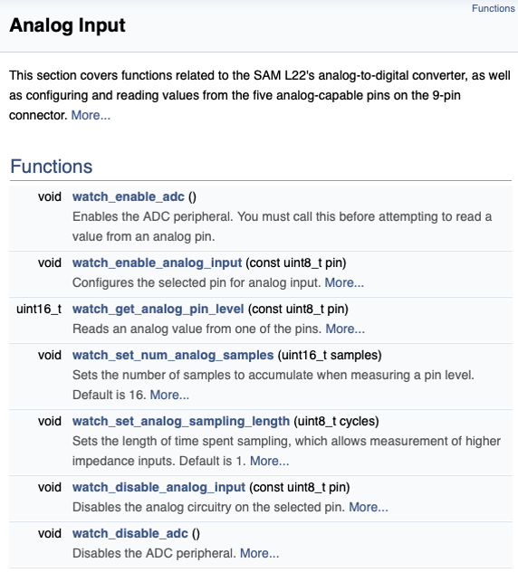
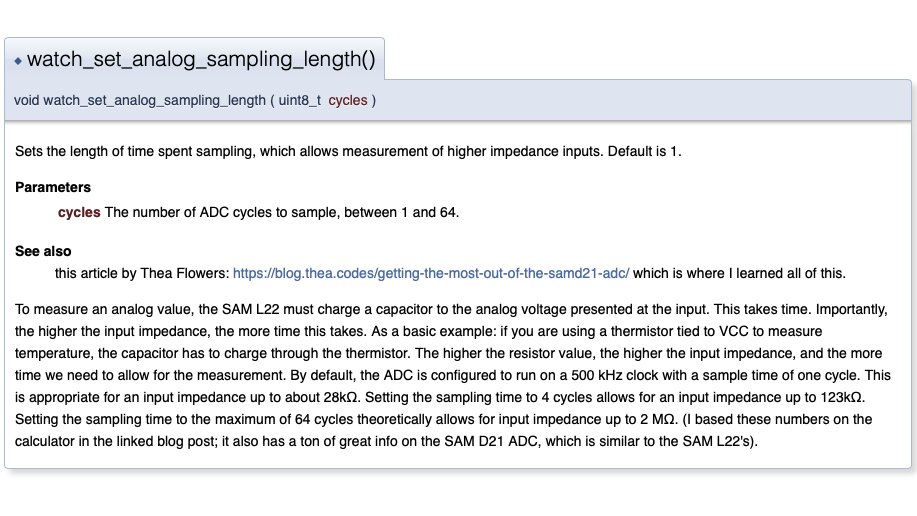
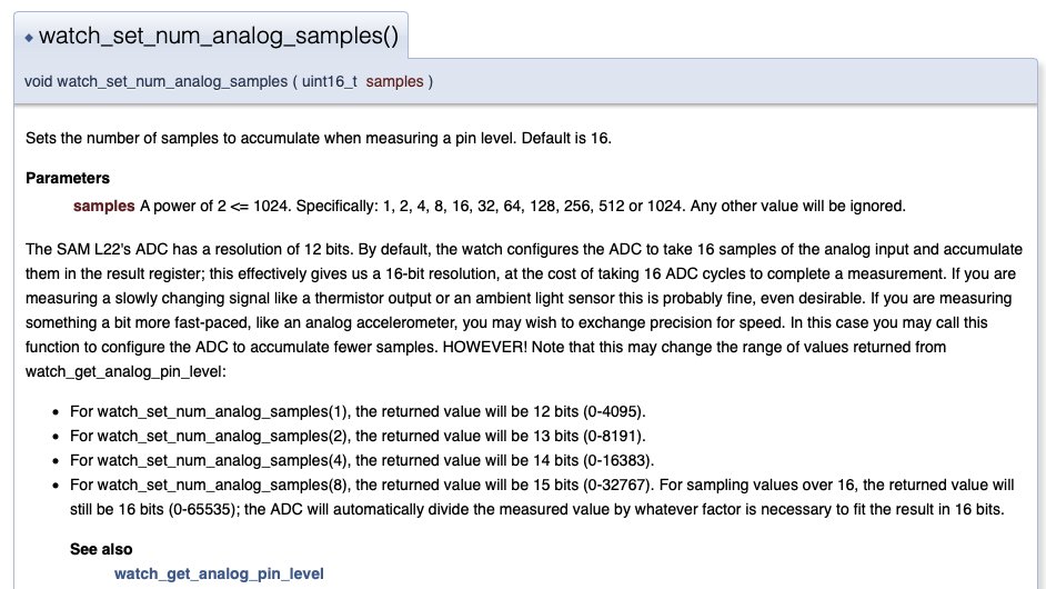
The documentation. Trying to strike a balance between keeping it simple, and offering lots of fine-grained control. also trying to offer just enough explanation of how it works to give folks a sense for when they might want to start tweaking the defaults… https://joeycastillo.github.io/Sensor-Watch-Documentation/group__adc.html
(original)
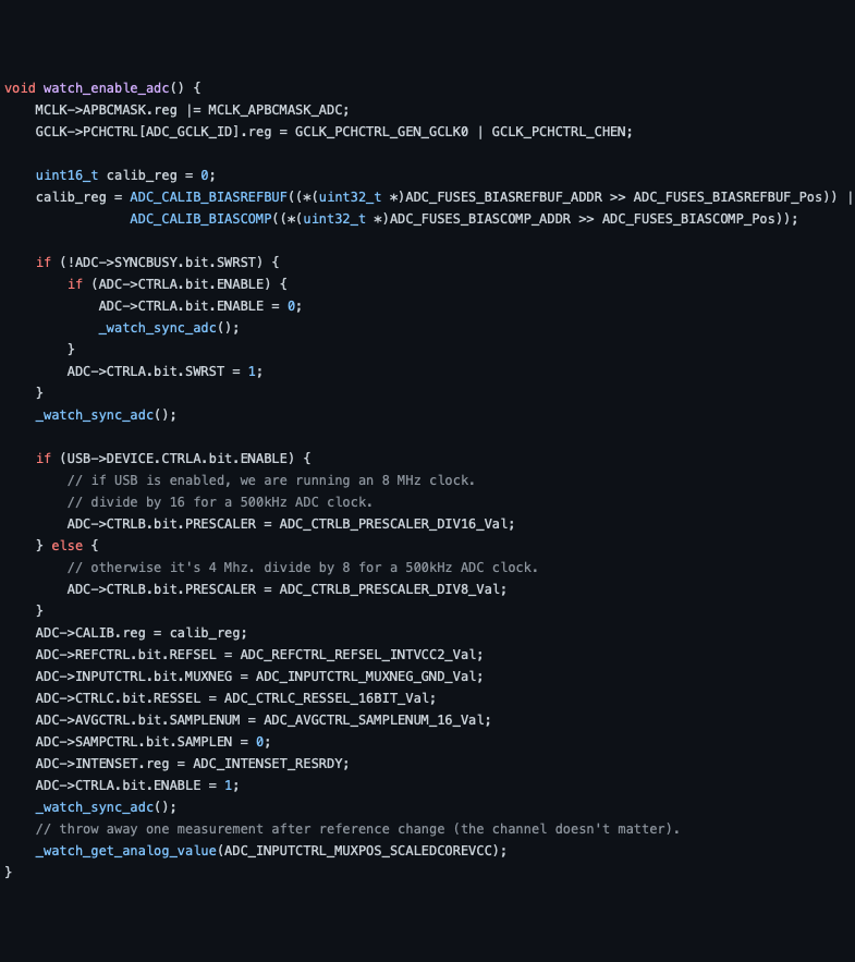
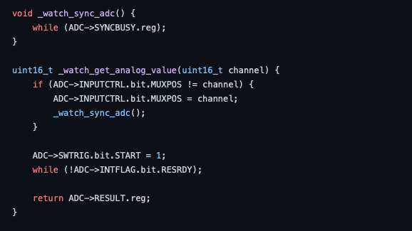
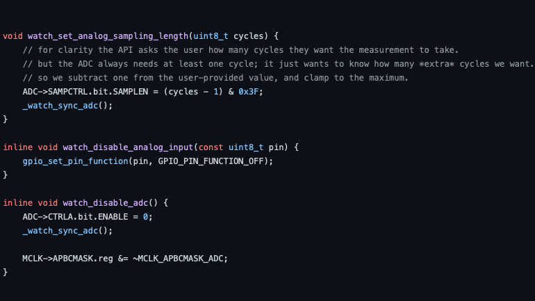
had a good weekend: traveled back to NYC, caught one last beach day, and oh yeah, implemented ADC functionality in the watch. i’m pleased with this. 133 lines of code, working directly with the registers in a way that I hope is readable and comprehensible. https://github.com/joeycastillo/Sensor-Watch/blob/main/watch-library/watch/watch_adc.c
(original)
Replying to @tarahaelle
any threat, any movie. Even in Idiocracy: when confronted with science-based evidence on the crops crisis, President Camacho changes his mind, stands up to the Brawndo lobby and implements a politically unpopular plan to stop salting the earth. That’s how you know it’s fiction.
(original)
Replying to @josecastillo
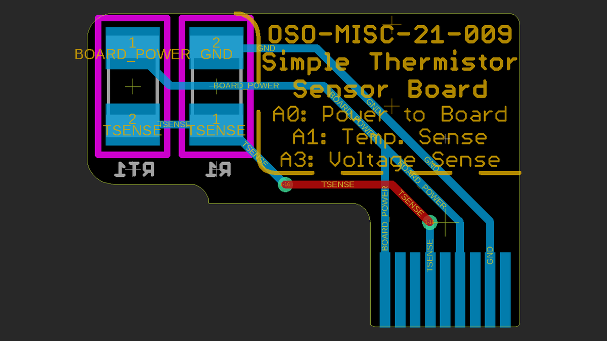
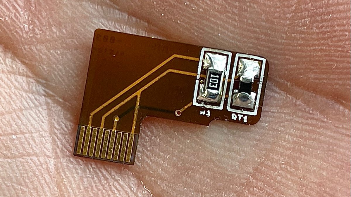
First things first: the simple thermistor board. It’s just a 10K NTC thermistor and a 10K 0.1% resistor configured as a voltage divider. I designed it to be super simple to DIY: 1206 footprints, lots of room to work. Something anyone can build at home with basic soldering skills.
(original)
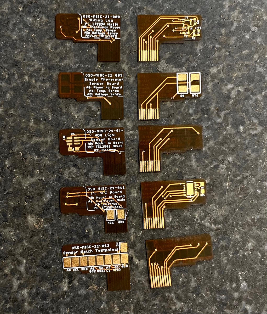
Yay! @oshpark has purple envelopes again! Nature is healing. Back at the shop; delivered today: good things in small sensor packages. Four new concepts for the watch: temp + motion, light, and connectivity (using an I²C programmable NFC EEPROM). Also more test point breakouts.

(original)
Replying to @dcelectr and @kicad_pcb
no thoughts on how to pull it off but can confirm: it’s a cool look 😎
(original)
I’ve never seen the wing in black on white soldermask; this color scheme slaps! https://twitter.com/gregoryknauff/status/1436435847755309071
(original)
Replying to @NanoRaptor
5, 6, 9, 10, 11, 12, 13.
(original)
Replying to @theavalkyrie
your tweet reminded me of this passage by the incomparable James Mickens:

(original)
Replying to @andrew_sears, @AlSweigart and @theavalkyrie
i’m not too proud to admit that I know exactly one vim command and it’s :q!
(original)
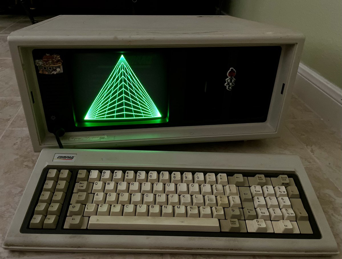
the artifact is staying in Texas, but I had to document this 1982-era demo, “Space Spiders”, that shipped with the Compaq Portable. The BASIC program listing credits programmer James B. Penny.
I love that while this was a machine for business, there was room on the disk for art.(original)
Replying to @crulge
I was at dinner with some co-workers a few years back where one was wearing google glass. The table was pretty evenly split discussing the tech, until glass guy revealed he’d been recording the conversation. To this day I’ve never seen that many opinions change that quickly.
(original)
Replying to @josecastillo
I get that modern processes are complex; a touchscreen is not a foam pad. We’re not going to be able to design everything screwdriver-ready and fabricable in one’s kitchen. Still, if we did build modern gadgets around that constraint… I’d like to see what they look like. /thread
(original)
Replying to @josecastillo
like obvs the low bar is a modern MacBook, where one broken key means replacing the keyboard, logic board, trackpad and battery. But I also had a switch fail recently in a new mechanical keyboard, and I sense I’m gonna need a soldering iron and a very specific replacement switch.
(original)
Replying to @josecastillo
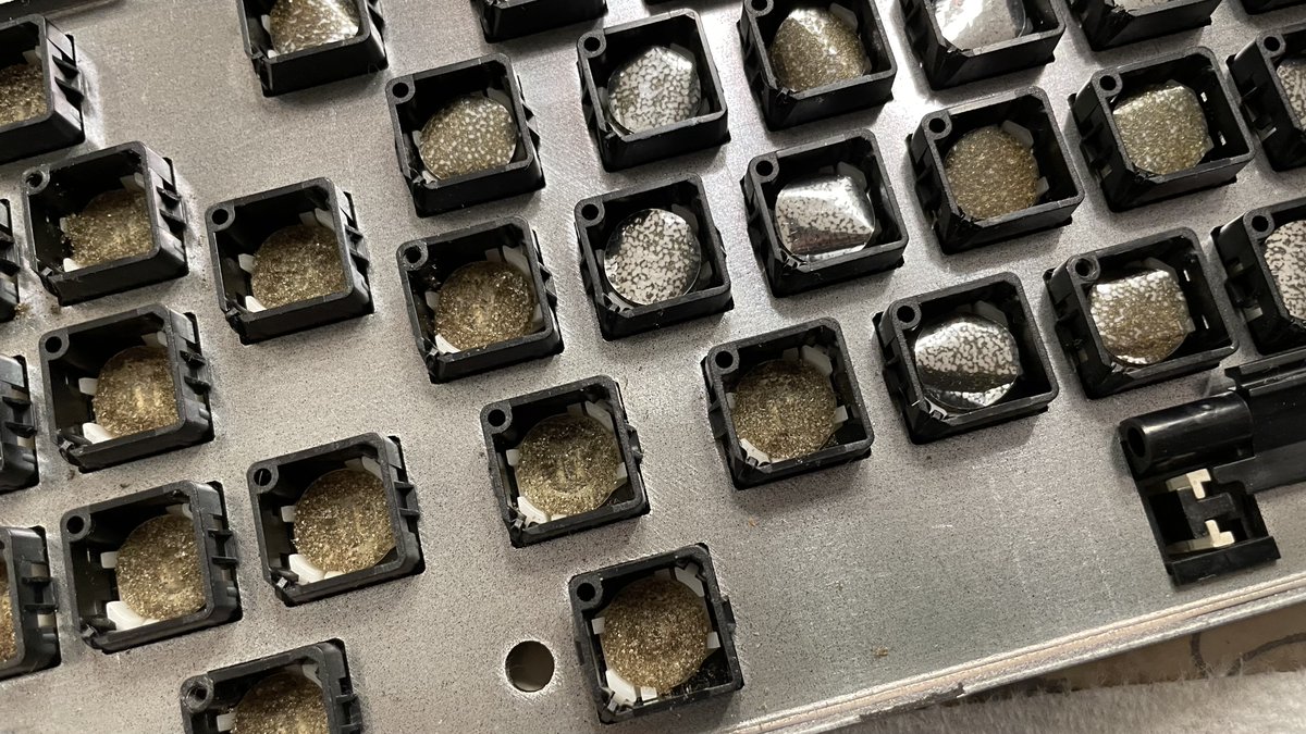
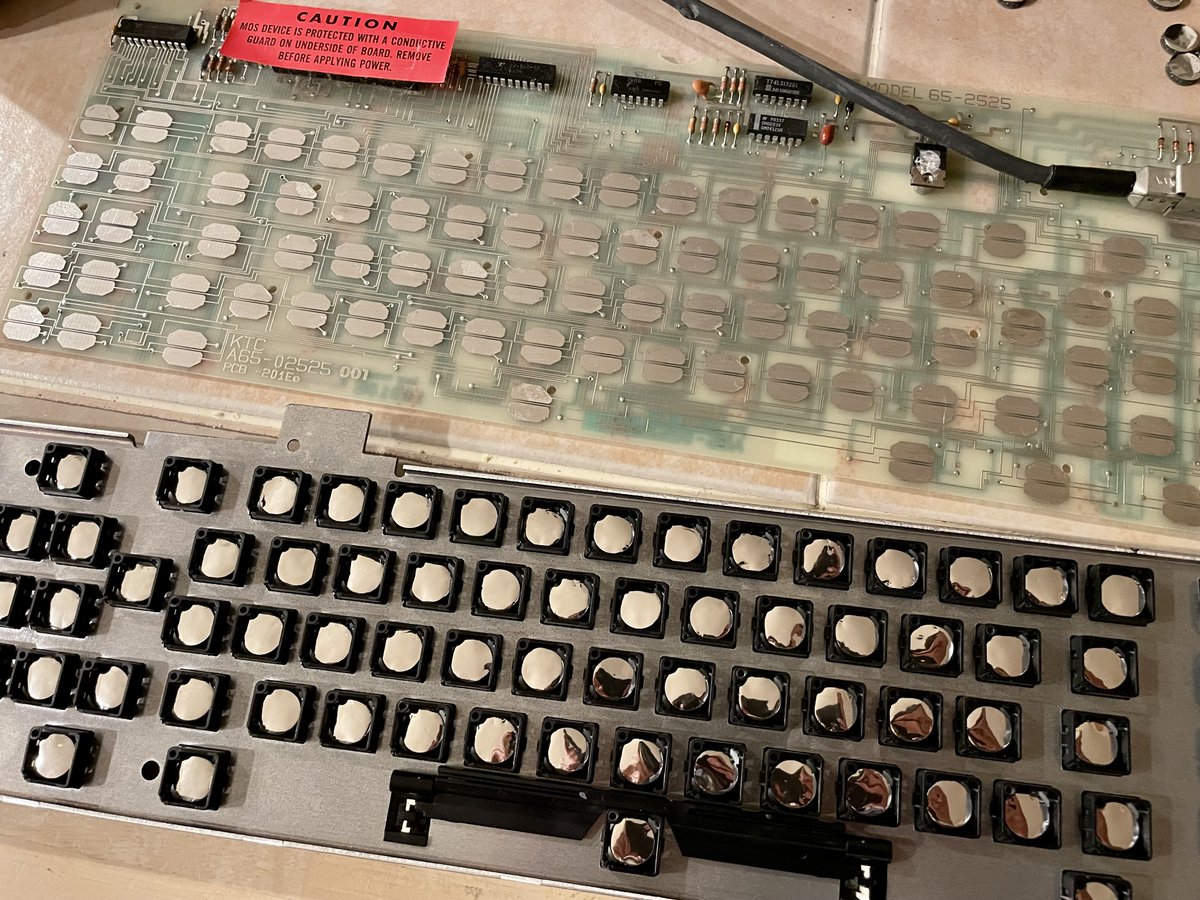
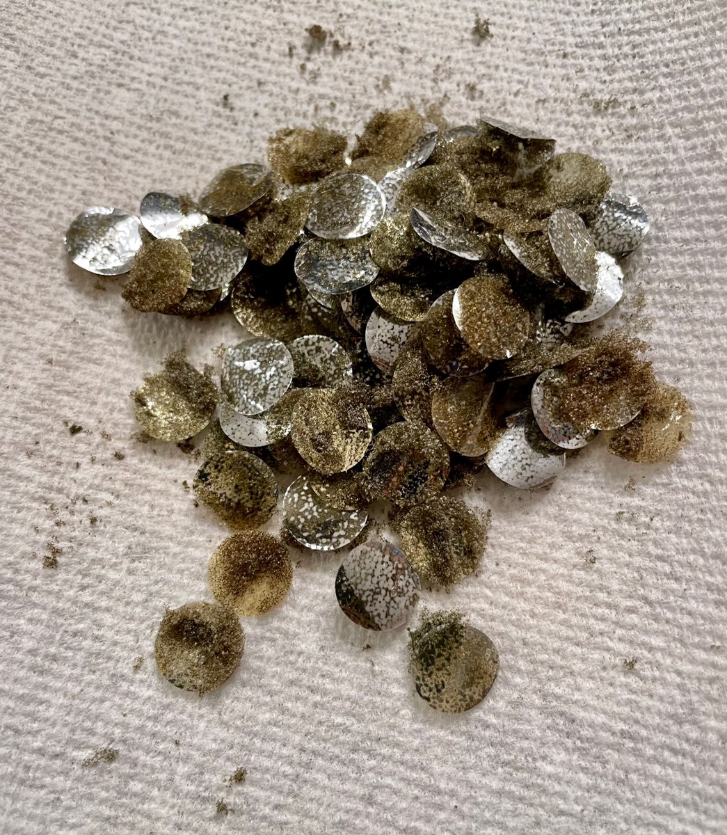
To do it, I used this 105-pack of “homemade in house” replacement pads. I like that the design is so comprehensible (and the materials so ubiquitous) that 40 years later someone was able to make replacements at home with some Mylar sheets and a hole punch. https://texelec.com/product/foam-capacitive-pads-keytronic/
(original)
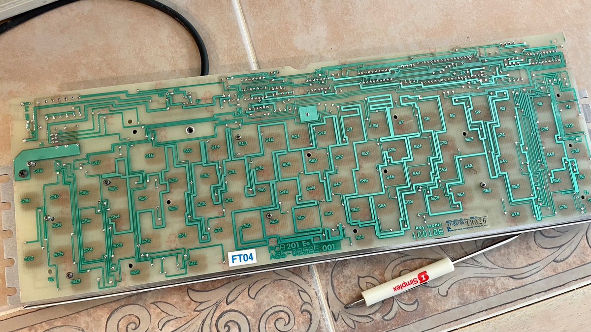
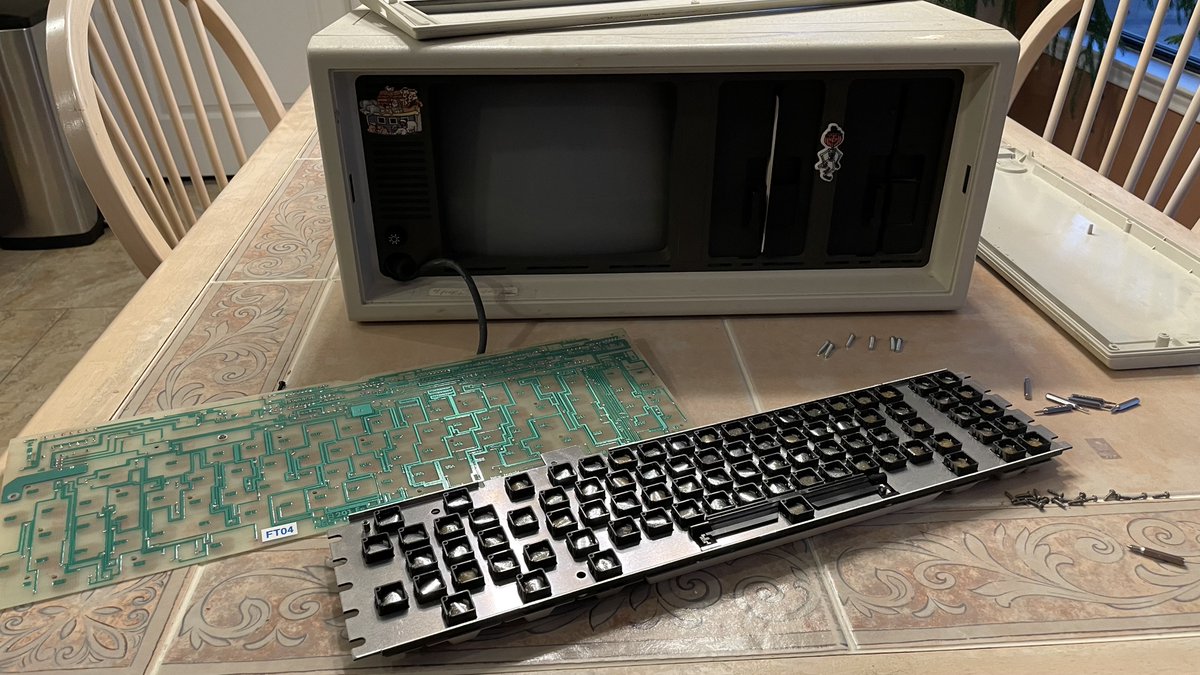
last night I fixed the foam-and-foil keyboard in my old Compaq Portable, and it’s given me some thoughts on repairability. I guess we stopped using these because the foam pads degrade over time? Sure, everything does. The thought is about what happens when they inevitably do. 1/4
(original)
Replying to @audreydodgen
Kid had the right idea. grownup’s still figuring it out :)
(original)
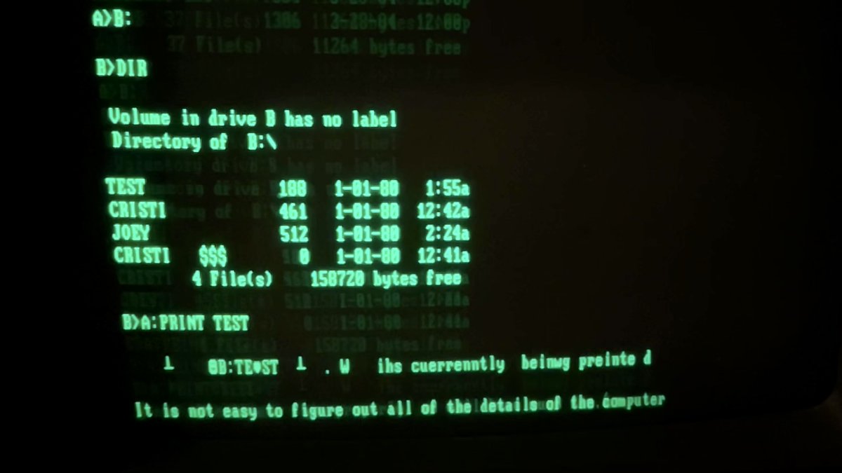
Revived my first computer; found wisdom on a 5¼ floppy I must have last touched at age eight:
“When we are able to use this properly, we will have much fun.
It is not easy to figure out all of the details of the computer.
But we will continue to try until we master the skills.”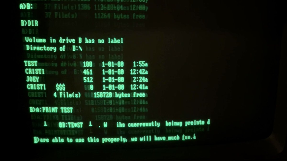
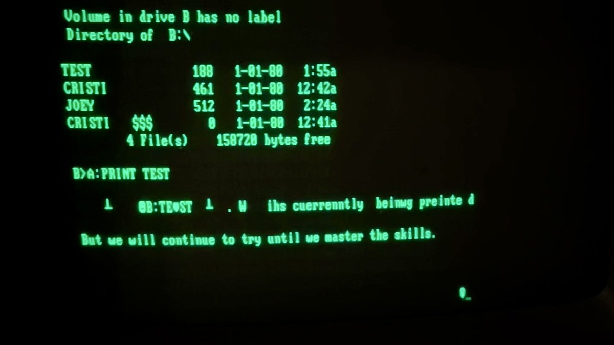
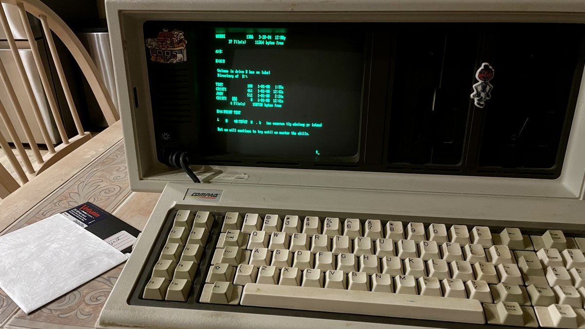
(original)
Replying to @josecastillo
Fixed the keyboard and my god, the floppy drive works! These files (and the disk drive for that matter) predate my birth. And before you ask, I ran demo.bat. it’s awesome, very 80s; I’d forgotten about it until just now.
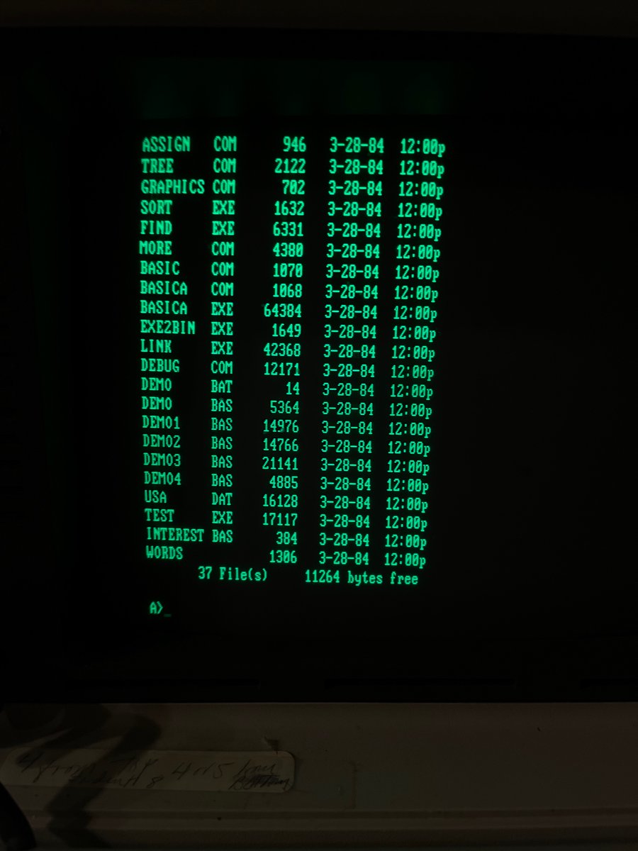
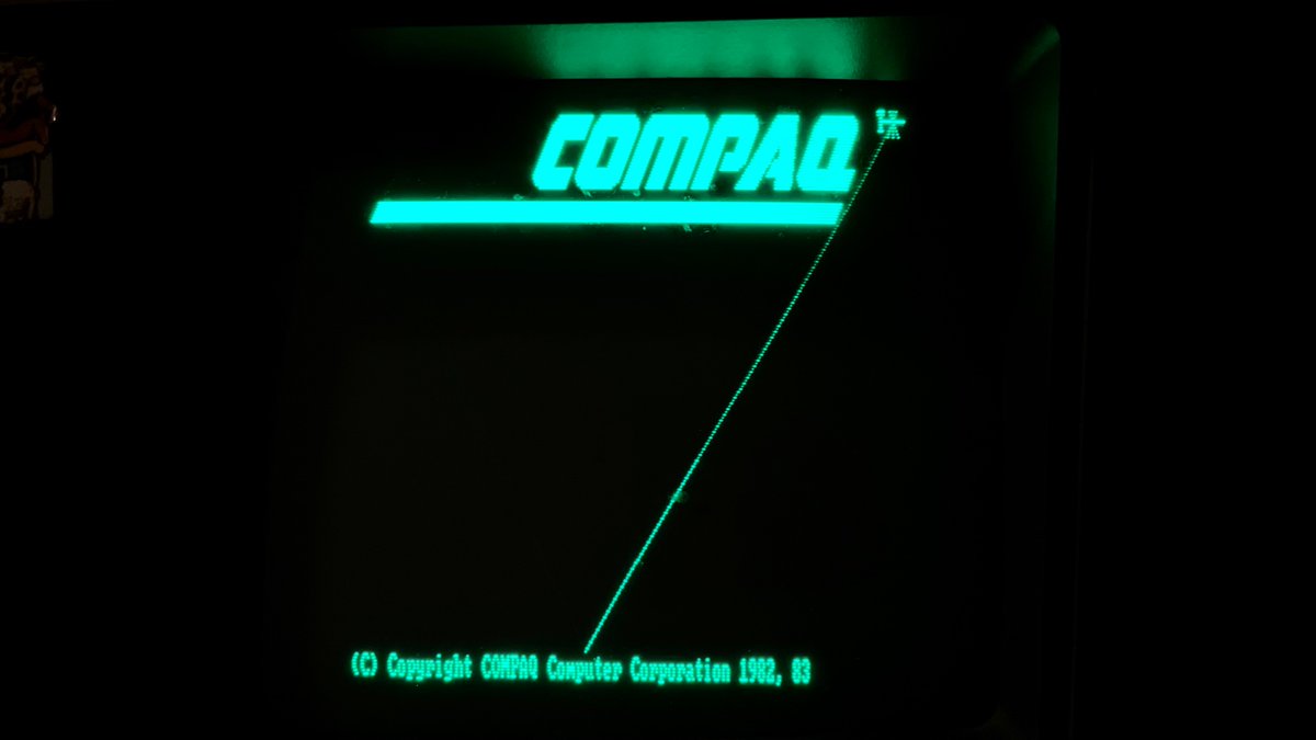

(original)
Replying to @josecastillo
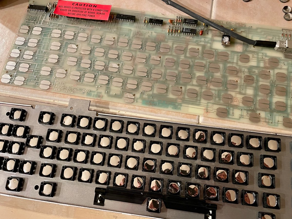
Shiny.
(original)
Replying to @josecastillo
Replaced the foam and foil pads on the number row, hyphen and colon keys just to make sure I’m on the right track. So far so good: I can set the date! Forgot to replace the foil on the shift key, though, so I can’t set the time. Yet.
(original)
Replying to @heyspacebuck
All credit there to the folks behind the Pluto watch! It was my starting point for the geometry of the F-91W PCB: https://github.com/carrotIndustries/pluto
(original)
Replying to @josecastillo
this is oddly satisfying. like popping bubble wrap
(original)
Replying to @heyspacebuck, @pdp7, @devoopes, @bateskecom, @glowascii and @oshpark
I haven’t tried it! I’ve been using ENIG and I’ve noticed some wear, but haven’t felt worry yet; in my design, I imagine the USB port only getting used rarely, so I hope it isn’t a big deal. The note on wear does give me pause, tho, thinking about my edge-plated button contacts…
(original)
Replying to @josecastillo
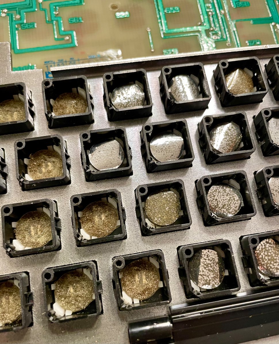
It’s a foam-and-foil keyboard. The last time I used this machine in the early 2000s, a couple of keys were failing; I just didn’t know why. Twenty years later, the foil is hopelessly tarnished, and the foam has crumbled to dust.
(original)