Tweets
I did my best with the time I had. Sent out 4 of the 5 boards I aimed to give out. Worked on the manufacturing piece. Polished the watch library. But now I’m taking a break: 5 days camping at a bucket list park. (i am writing code on the plane. but it’s pencils down when I land.)
(original)
Replying to @ConfuSomu
I laid out the document with the excellent @affinitybyserif Publisher for Mac, and did the board illustration using Affinity Designer, Inkscape and an assist on the board illustration from Tracespace’s Gerber Viewer: https://www.gerberviewer.io
(original)
Replying to @IoTPanic
haha. The funny part is, you would really have to go out of your way to do this. when the watch is clipped in with a battery there’s no way to get to the USB port, and no room for the plug to fit even if you could. But I figure you should never underestimate people’s ingenuity :)
(original)
Replying to @AndrewVall
The lazer bear? Well, the name is “Oddly Specific Objects”, acronym OSO, which is bear in Spanish. With that decided, I thought she needed laser eyes, a bionic leg and a shark for an arm (because it’s awesome!); then I commissioned a colleague (@DoctorDevens) to do the artwork :)

(original)
Replying to @josecastillo
There’s always more to do when it comes to documentation. But I can feel myself getting closer.
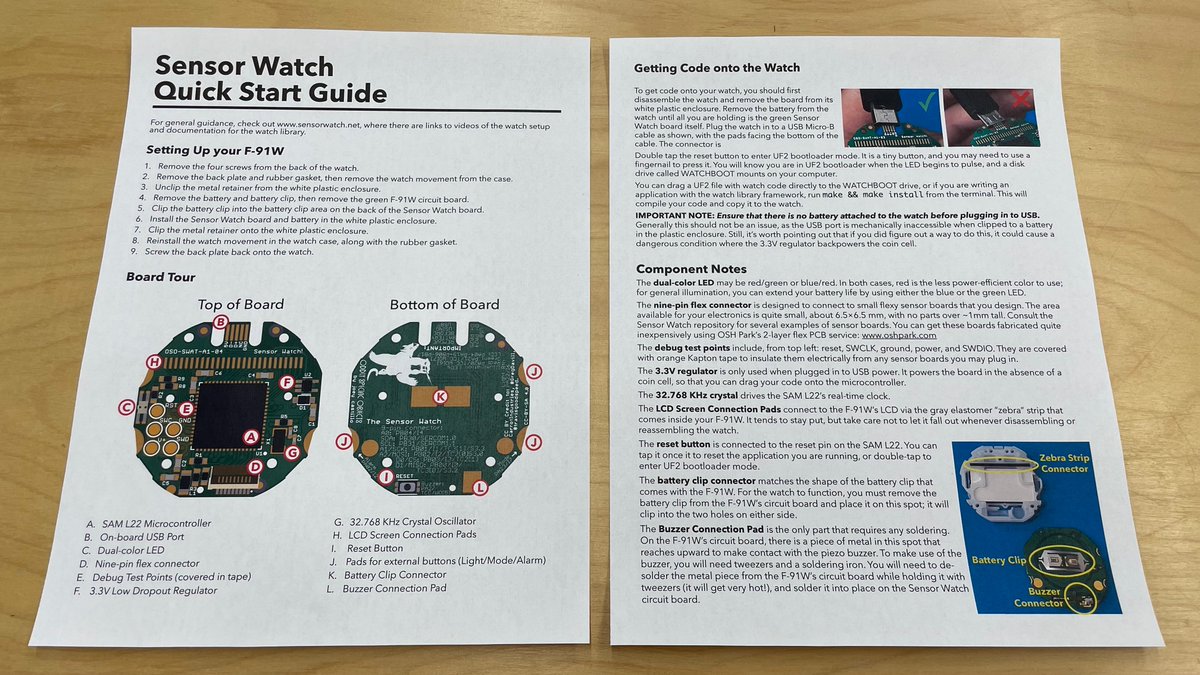
(original)
Finally got around to making a diagram of the watch with all components populated. I like this look; feels very satisfying.
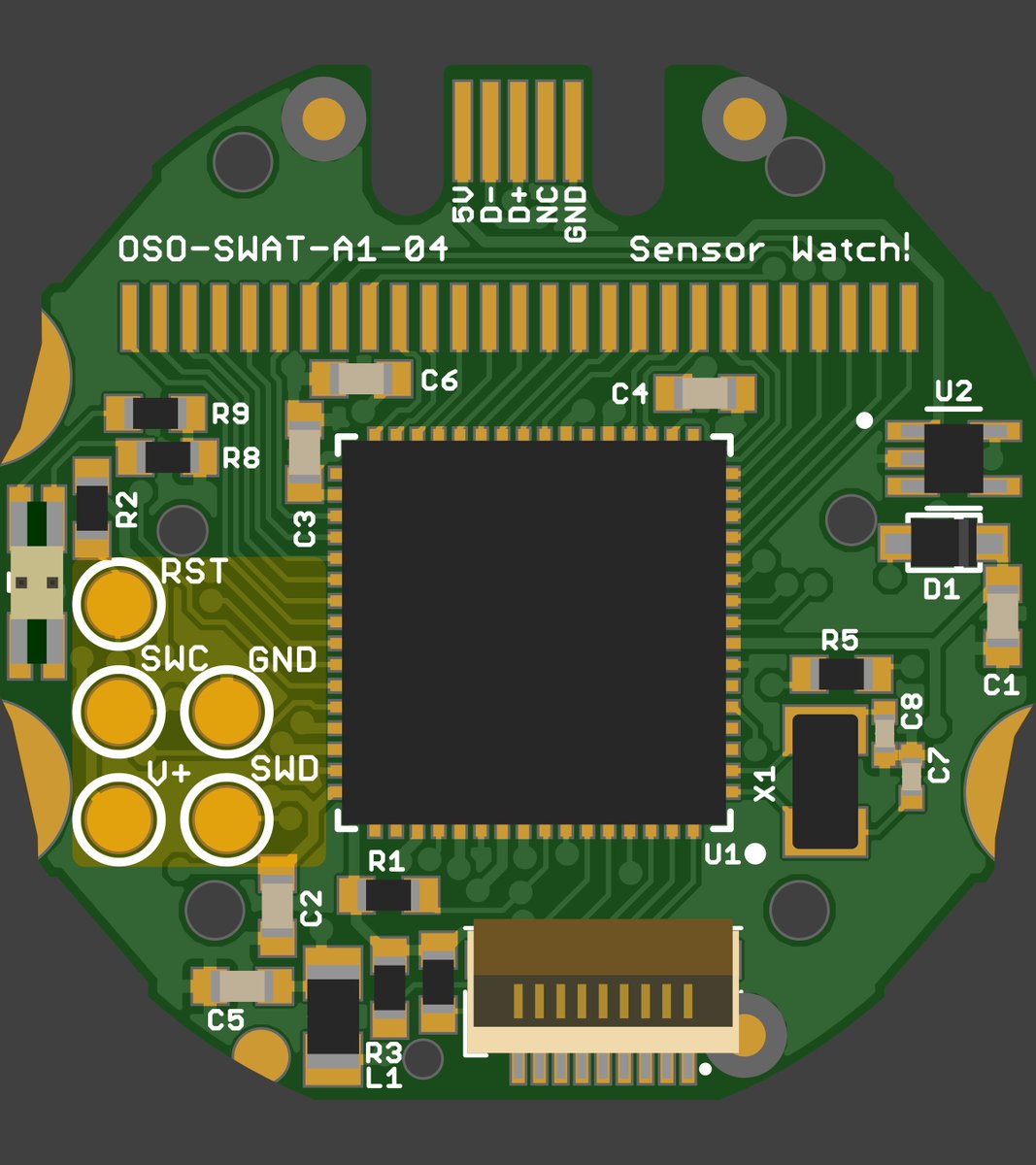
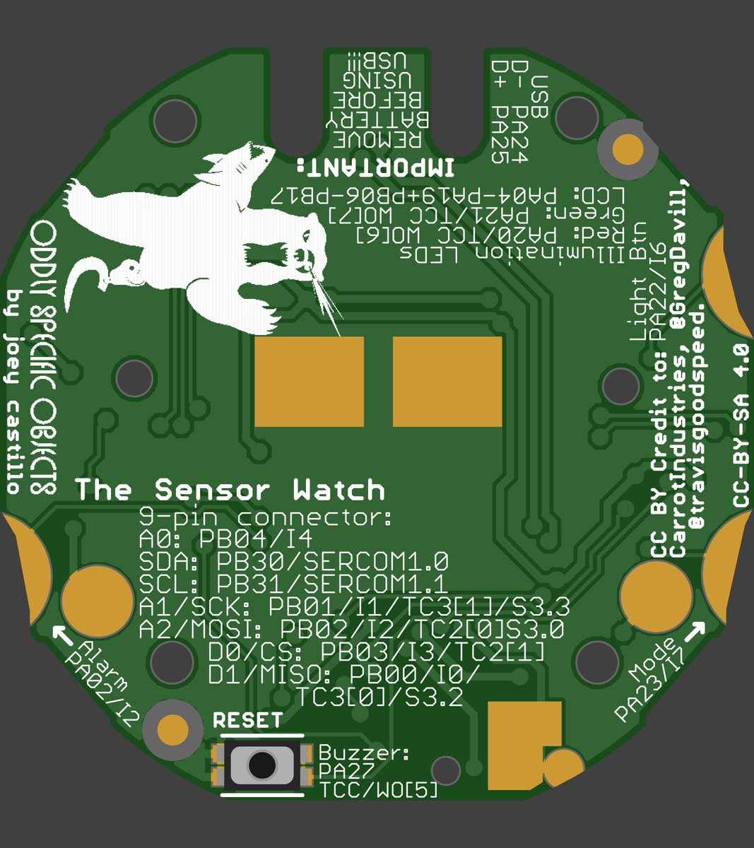
(original)
Replying to @peppertronics
If you want to write a clock mode into your app, you can do that! But it’s kind of all up to you. I actually plan to add a clock mode to the BME280 app; I want to have it log temperatires and play back with timestamps; if I’m going to be keeping time, might as well add a clock :)
(original)
Replying to @NiVZ
I mean I can’t make you follow through with anything, but if you’ve got an idea in your head and the kit to make it real, I figure hey, maybe it’ll happen!
(original)
what if forks were searchable? https://twitter.com/GithubProjects/status/1426795600071122947
(original)
Okay! My plan for the first five Sensor Watch boards: I’m going to give them away. Fill out this form with a short answer about what kind of app you want to wear on your wrist. I’ll leave this open for the next day or so and pick five recipients tomorrow. https://forms.gle/2y1kZeEZj9xdtvG1A
(original)
Replying to @ancient_james
I sense that the three on the right relate to tuning the crystal, given that they’re all tied to one of its pins. The ones in the bottom center, I don’t know. I tried opening and closing some and couldn’t discern any changes.
(original)
Replying to @josecastillo
Ended up catching two failures: an LED with one bad connection, and a bridged pin on the QFN that was preventing the crystal oscillator from ticking. Both easily fixed :)
(original)
Sensor watch test procedure, featuring the Pycorder. Lights up red at the start, then tests:
- reading a byte from an I2C device,
- reading levels from each of the pins on the 9-pin, and
- Reading a press of each of the side buttons.
Also tests both LEDs and the debug UART.
(original)
so this appeared on our wall last night
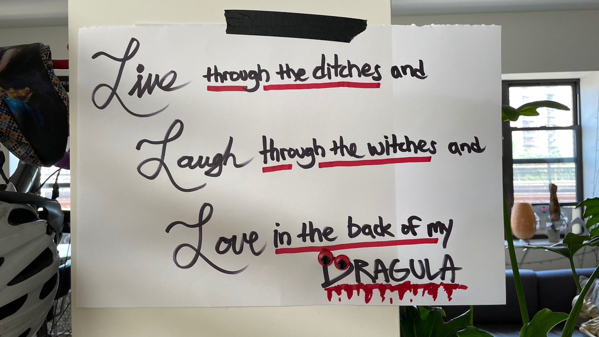
(original)
Replying to @Tonejito
https://twitter.com/josecastillo/status/1426369279688069125?s=20
(original)
Replying to @OGthrombus
With the first firmware rev I got three months. But I’ve improved the standby current consumption since then. It’s tough to give an exact number since the intent is for folks to write their own applications for it; your mileage may vary dramatically :)
(original)
Replying to @normalvisual and @MakeAugusta
so far I’ve designed a motion and an environment board (temperature, humidity) to plug in to the flex connector. My next goals are a light sensor and an NFC chip, and maybe a simpler temperature sensor that’s easier for folks to DIY.
(original)
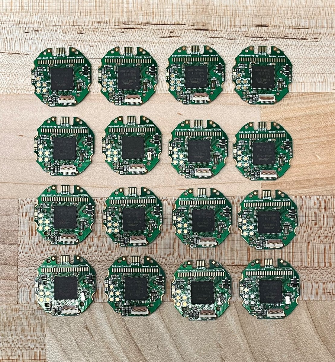
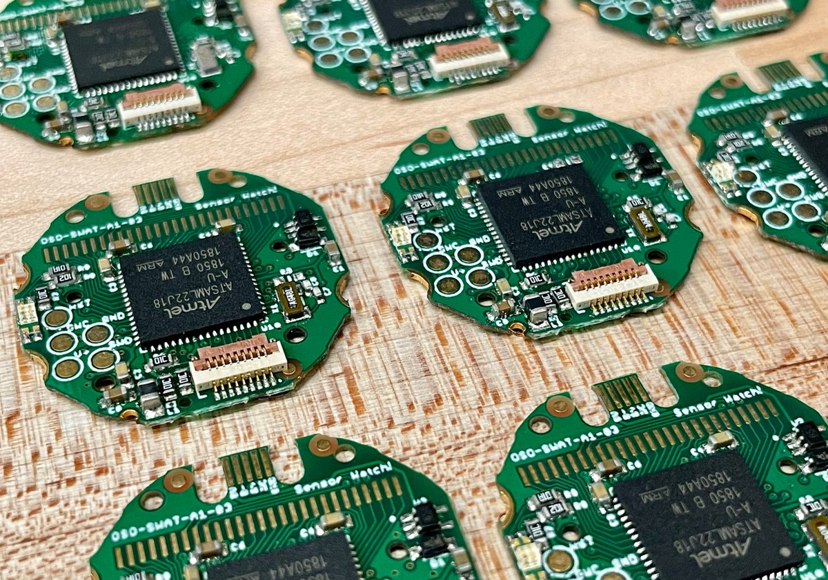
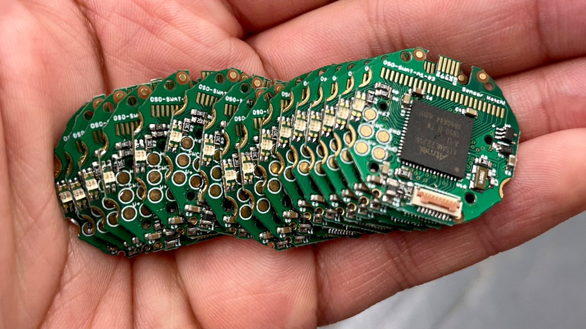
Friday afternoon sense of accomplishment: sixteen fully assembled and functional Sensor Watch boards. I swear I have a plan for these. More soon.
(original)
Replying to @_nitz, @Gadgetoid, @timonsku, @github and @Microsoft
25 now :)
(original)
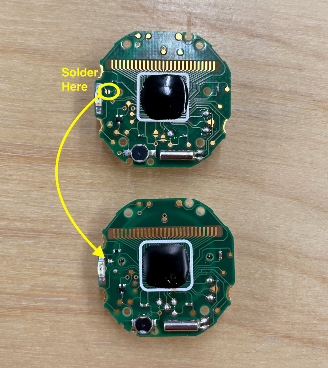
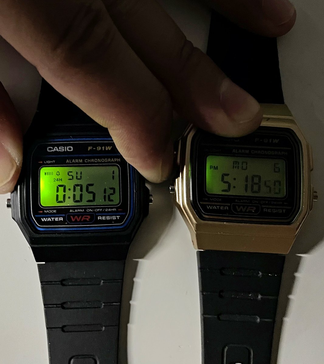
Fun Casio watch hack I discovered today: if you own an F-91W and find the illumination LED a bit anemic: take the watch apart and close the solder jumper at the top left. This bypasses the 170Ω current limiting resistor to deliver max brightness (and of course void your warranty)
(original)
Replying to @tahnok
At the end of the day I think I’ve reached the same conclusion. If the power consumption were the same between the two alternatives, I could see going for consistency. But battery life is the north star for a gadget with a fixed 100mAh budget; I can’t spare 3.3mA for consistency.
(original)
Replying to @samblenny
I think this may be more to do with the semiconductor technology (chemistry?) underlying these LEDs. The red and the less efficient green use aluminium gallium indium phosphide (AlInGaP) technology, whereas the blue and more efficient green use indium gallium nitride (InGaN).
(original)
i have assembled the new watch rev and fixed the long-standing USB issue.
(original)
Replying to @davedarko
It’s kind of fascinating but apparently custom LCD manufacturing is a pretty commoditized service? I mean it makes sense; there are so many cheap gadgets out there with custom LCD’s. All they had to do was find someone with the will to blatantly counterfeit a watch face.
(original)
Replying to @keesplattel
I’ve always wanted one of those blackout watch faces! How did you come upon them, did you DIY them?
(original)
Replying to @josecastillo
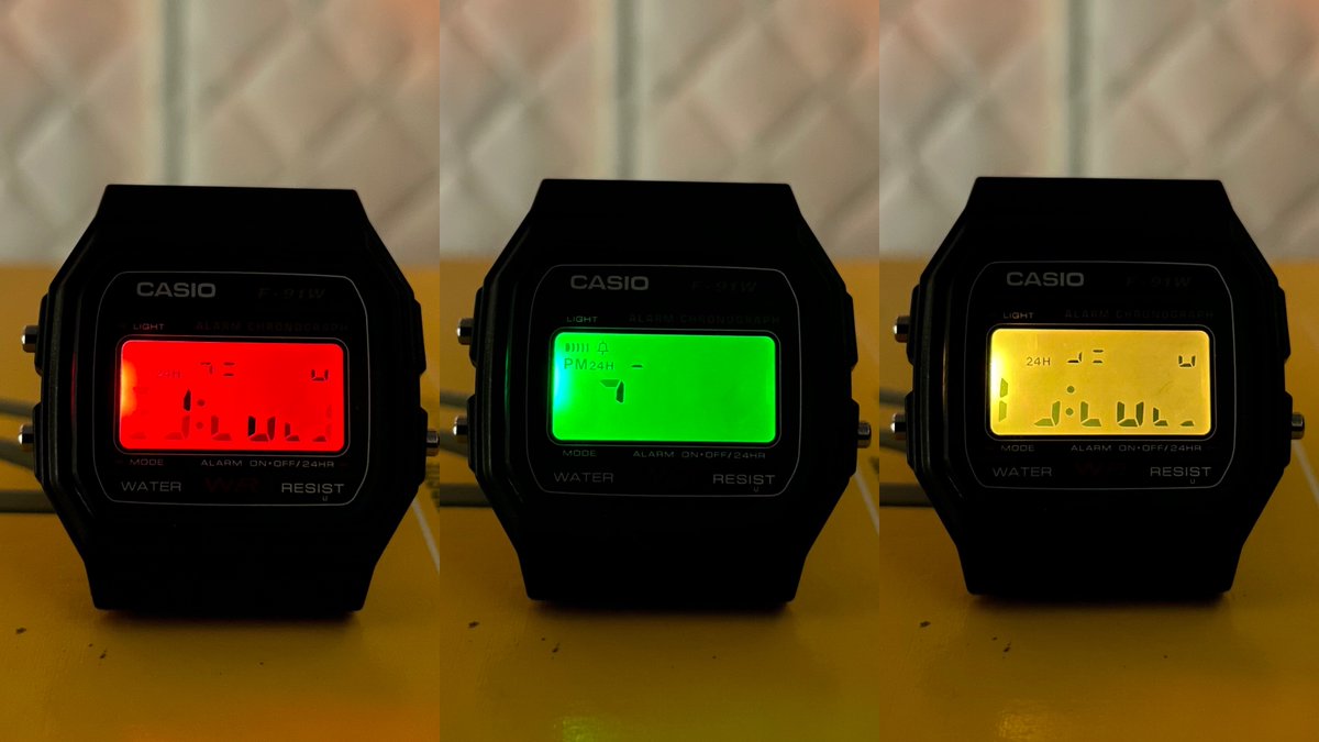
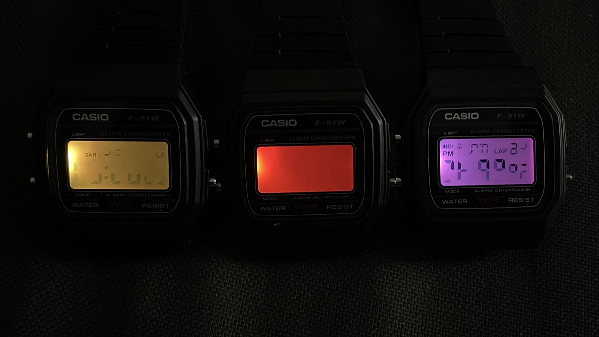
(oh and also, ignore the gibberish on the screens in this thread. turns out some of the cheap watches I bought on eBay were counterfeit, and the fake watches use a fake LCD that doesn’t match the actual F-91W segment map. Useless to me, except for testing LED colors, apparently)
(original)
Replying to @cabe_bedlam
Maybe! Definitely worth renaming the pins to LED_A and LED_B. As for the functions, maybe it’s enough to just add a note to the documentation: “On watches with a red/blue LED, this method sets the LED to red(/blue/pink).”
(original)
Replying to @kfury
I love the pink too. As soon as I saw it it called to me.
(original)
Replying to @josecastillo
I don’t know which way I’m going to to go on this one. My heart wants hot pink, but my head says keep it simple. But then, my head also says don’t chew up more power than you need to for what your eyes can see is a crappier shade of green.
This is going to be a tough one.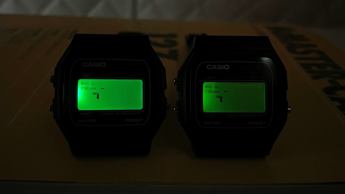
(original)
Replying to @josecastillo
Alternatively, the red/crappy green LED would keep the library code the same (with perhaps a note that set_led_yellow can show up orange on some boards) — but the extra power consumption offends my sensibilities, and could have a real impact on battery life for some applications.
(original)
Replying to @josecastillo
The pink version will add complexity to the library I’m writing. The
watch\_set\_led\_redfunction won’t be aware of which watch it’s targeting, so setting the RED pin high will light the LED blue. Unless I add like ifdefs and a compiler flag, which is more complicated for folks.(original)
Replying to @josecastillo
In my imagination, this workaround is only going to be a thing for the first run of 100; hopefully soon the original LED will come available and I can make more using that. So here’s the tradeoff discussion: a drop-in replacement I’m not wild about, or a cool one-off alternative.
(original)
Replying to @josecastillo
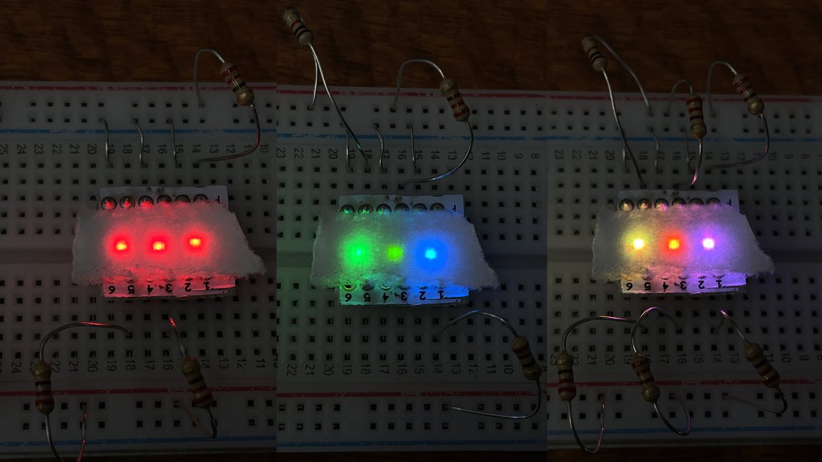
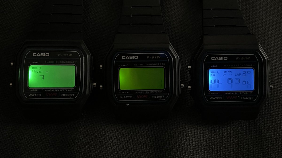
Contender #2: Red/Yellow-Green (+orange). The pros: it’s drop-in compatible. The pinout matches, so RED and GREEN light up their respective colors. The orange does look killer. But the big strike against: green looks pretty dim, even at 4.5 mA. And I don’t want to give it more.
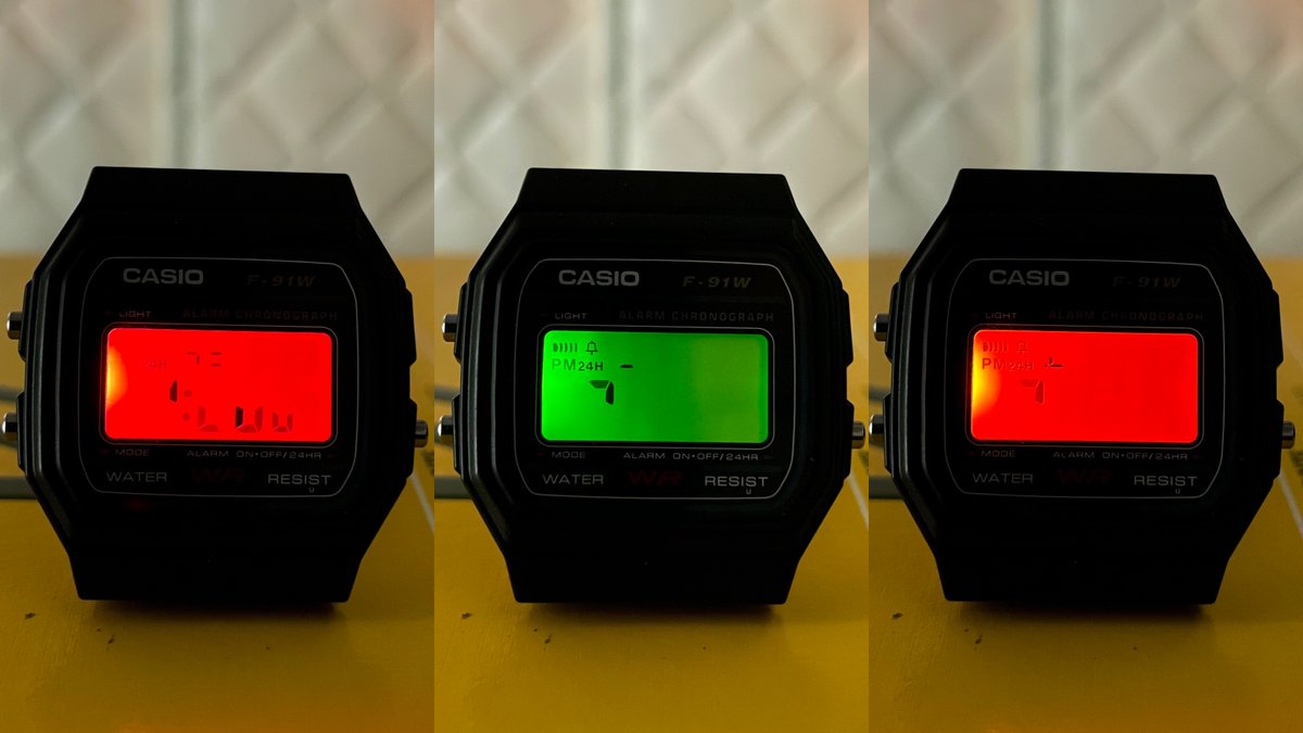
(original)
Replying to @josecastillo
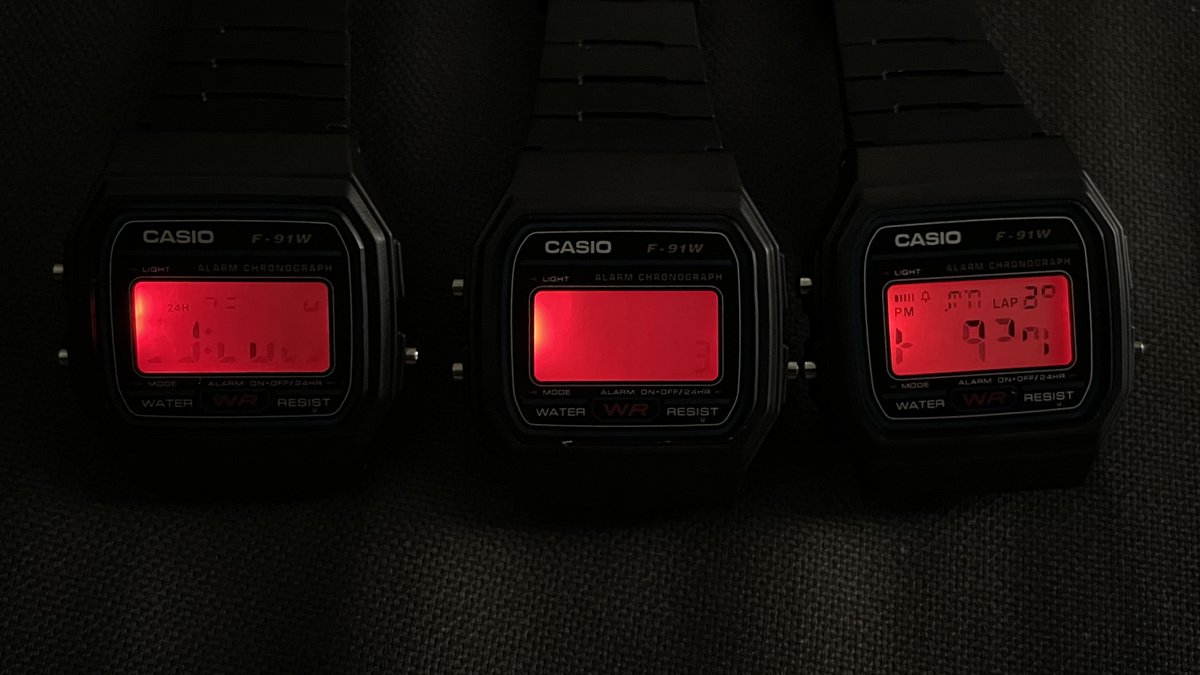
Contender #1: Blue/Red (+pink). First off, I like it. The footprint matches. It looks cool. And I can get decent brightness out of it at just 1.2 mA. One strike against it, tho: the pinout is switched. The pin I’ve been calling “GREEN” lights up red, and “RED”? It lights up blue.
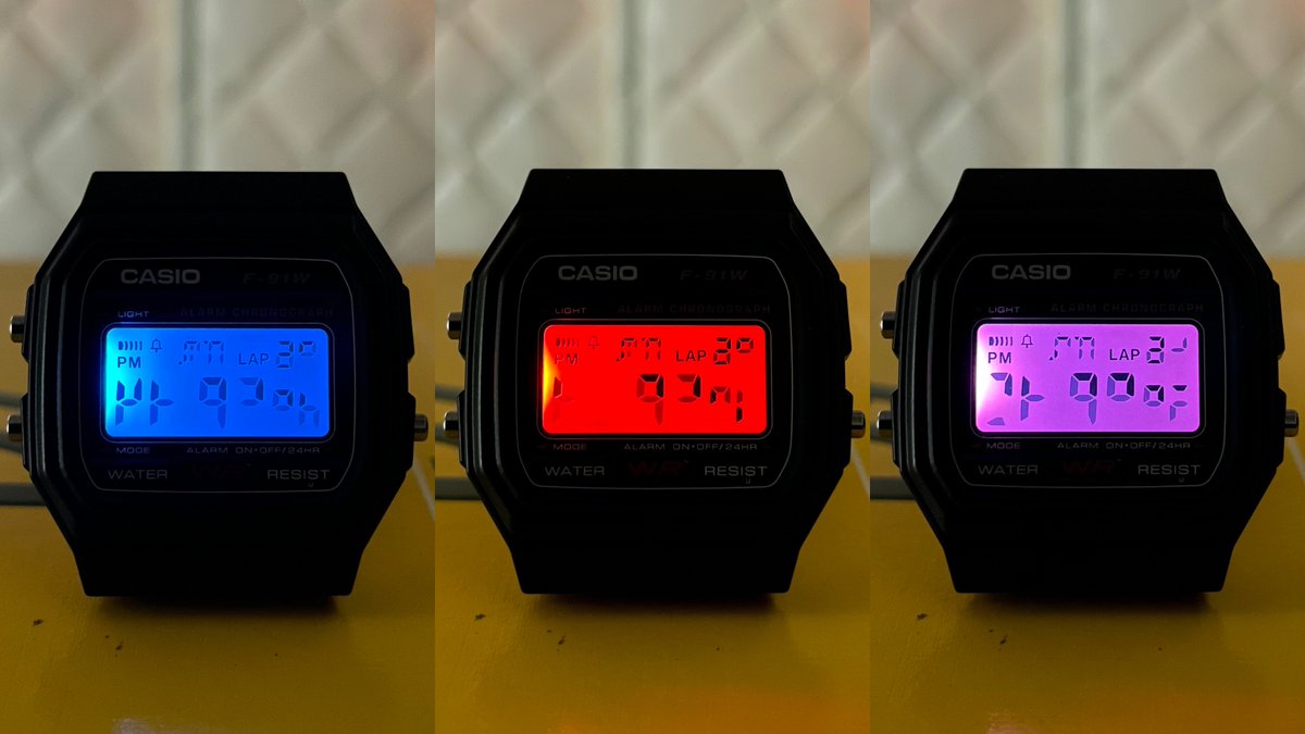
(original)
Replying to @josecastillo
First up: the original. First in my design, and my heart. The green here is a “true green”, not the yellow-green that’s common in indicator LED’s. But the real draw here is that while red needs ~4.5mA to shine, green can deliver serious brightness at a fraction of a milliampere.
(original)
evaluating two possible LEDs to replace my unobtanium RG(y) for this first run. Neither have the power efficiency that I loved the original one for. But TBH, both look rad in their own way. I talk about how engineering is about tradeoffs? This is a good one to unpack in a THREAD:
(original)
Replying to @jprodgers
Awesome!!
(original)
Replying to @DemmonShadowp
I’m gonna be honest, I haven’t done a lot with the Revision 0 ESP32-S2 book. Initial testing was with the Arduino core and CircuitPython, but that was months ago, and I sense that the state of the art has improved since then. I’ll report back once I have a chance to work with it!
(original)
Replying to @sneenyc
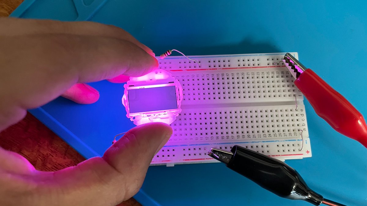
You were so right BTW. With 100 ohms on both, the blue appears way brighter than I expected, and they blend to a perfect hot pink. Promising!
(original)
Replying to @josecastillo
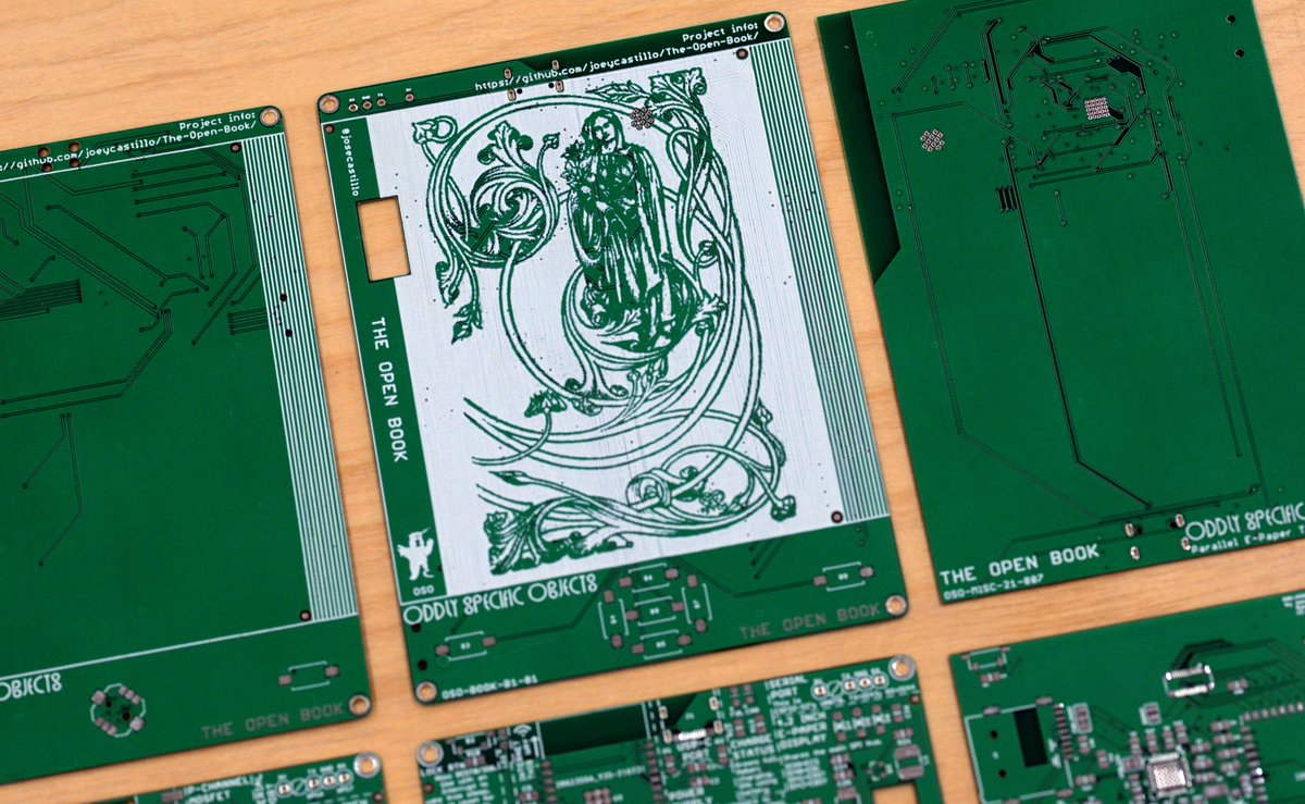
The artwork is public domain, endpapers from the Everyman’s Library, a 1900s-era project that aimed to create a collection of great books of the world that would be affordable by the common man. One of the founders called the effort “impracticable, quixotic [and] transcendental.”
(original)
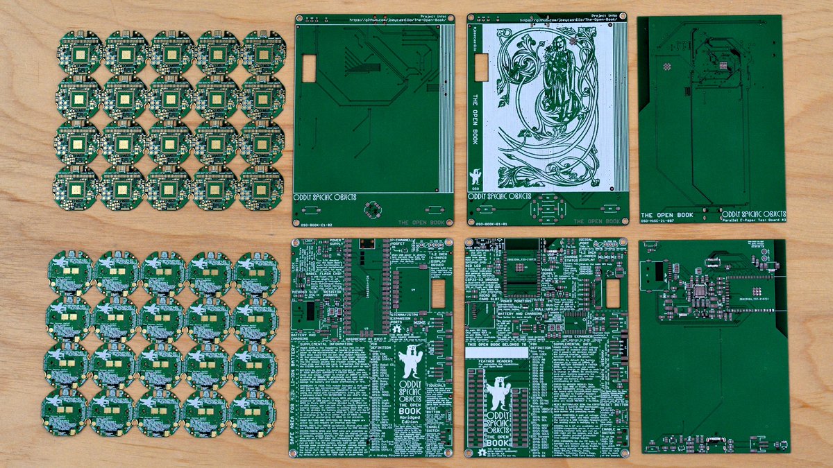
new watch boards are here! And because I can’t send an order overseas without including at least two other things: a new revision of the Pi Pico book, a proper “Revision 01” of the ESP32-S2 book, and what I hope to be third-time’s-the-charm with the parallel E-Paper test gadget.
(original)
Replying to @PatriceGirard
Atmel Power Debugger, generously lent to me by a colleague for this project. come to think of it, it’s been six months; probably need to get it back to him soon 😬 https://www.microchip.com/en-us/development-tool/atpowerdebugger
(original)
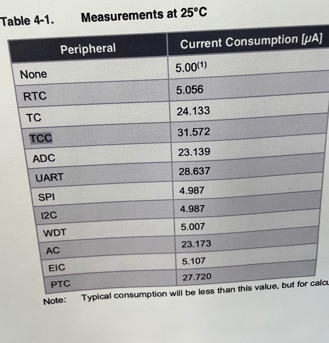
OH MY GOSH I AM AN IDIOT. Forgot that I left the debug UART on for all of my low power tests yesterday. With that off, baseline power consumption goes down to <66 µA. I even have this pinned to my wall, and the math hilariously checks out: 66 + 29 = 95.
So, that was a freebie.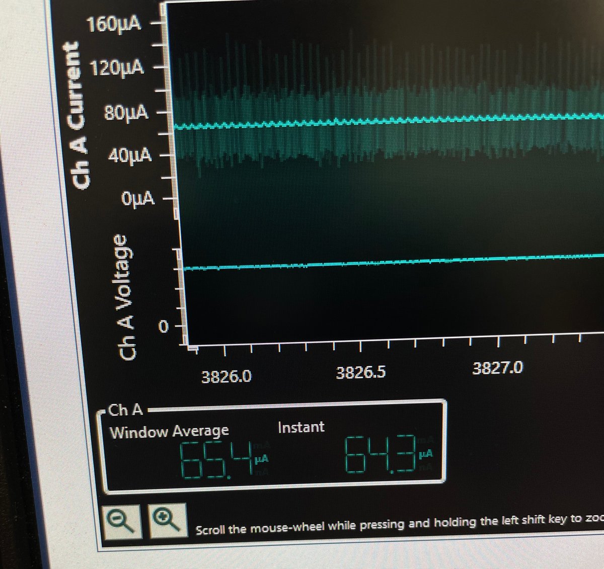
(original)
Replying to @mattk and @adafruit
Oh definitely and I have functions in the library for PWM’ing the LEDs. This is just about figuring out max brightness at full power. I’d also like to use a specific value for each, if only to be able to say “at full power, red + green = yellow”; I want to make it easy for folks.
(original)
Replying to @sneenyc
interesting! I had no idea. Definitely stoked to solder one onto a breadboard and see what it looks like. It’s all subjective anyway; my plan is to just tweak the output until I get a really mauvy shade of pink.
(original)
Replying to @josecastillo
Anyway. We will see. Circuit boards with the hoped-for USB fix arrive today, along with ten red/blue LED’s from Digikey for testing. If all checks out, I think I’m going to order all the rest of the parts for the run of 100 before I skip town for a long camping weekend next week.
(original)
Replying to @josecastillo
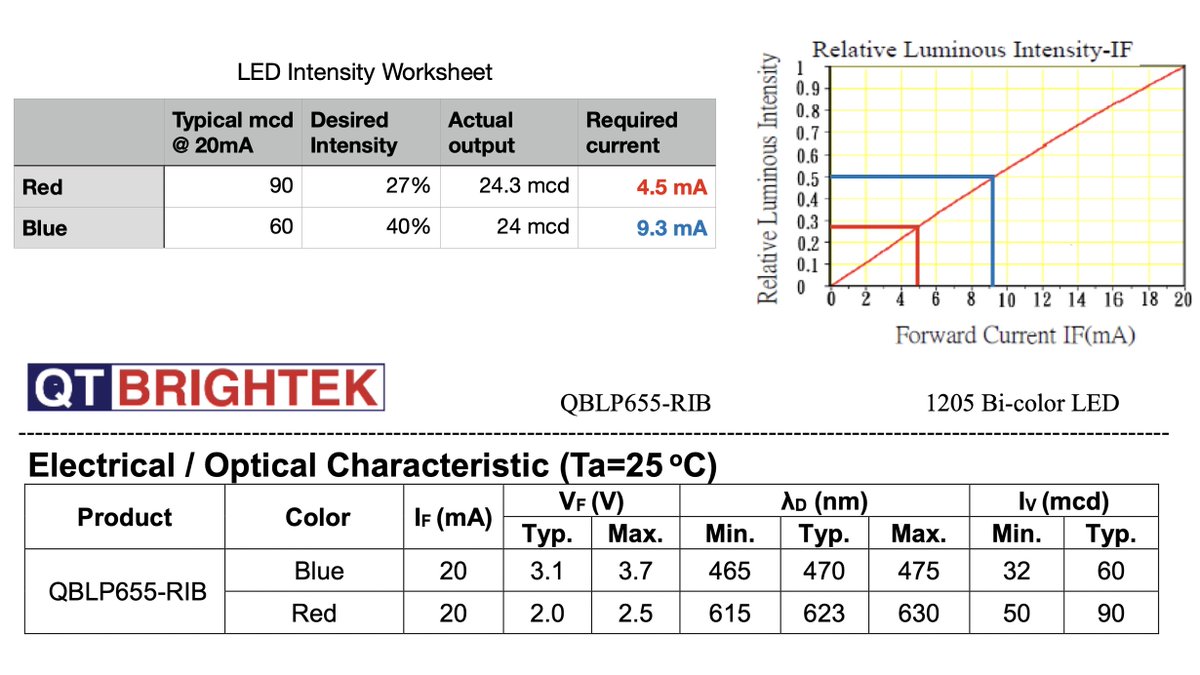
This is actually iffy news for the red/blue variant I’d hoped would fix my supply chain woes. It could work; I still plan to test. But blue is likely to be EVEN LESS efficient, and pink could consume 3x as much power as yellow (which itself consumes 50x the watch’s standby power)
(original)
Replying to @josecastillo
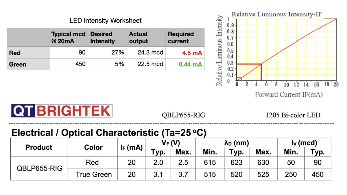
There are two LED’s in this bi-color LED, with different characteristics. The green maxes out at 450 mcd, but the red only hits 90 mcd. This means green can hit my desired brightness at 5% of its maximum intensity, but red needs to hit 27%. That means more current and more power.
(original)
Replying to @josecastillo
So, back to the watch: it may seem counterintuitive that the red LED consumes 10x the power of the green. But that’s only because I designed it that way: the green LED is limited with a 1K resistor, while the red is limited with a 100Ω resistor. To see why, we need another table.
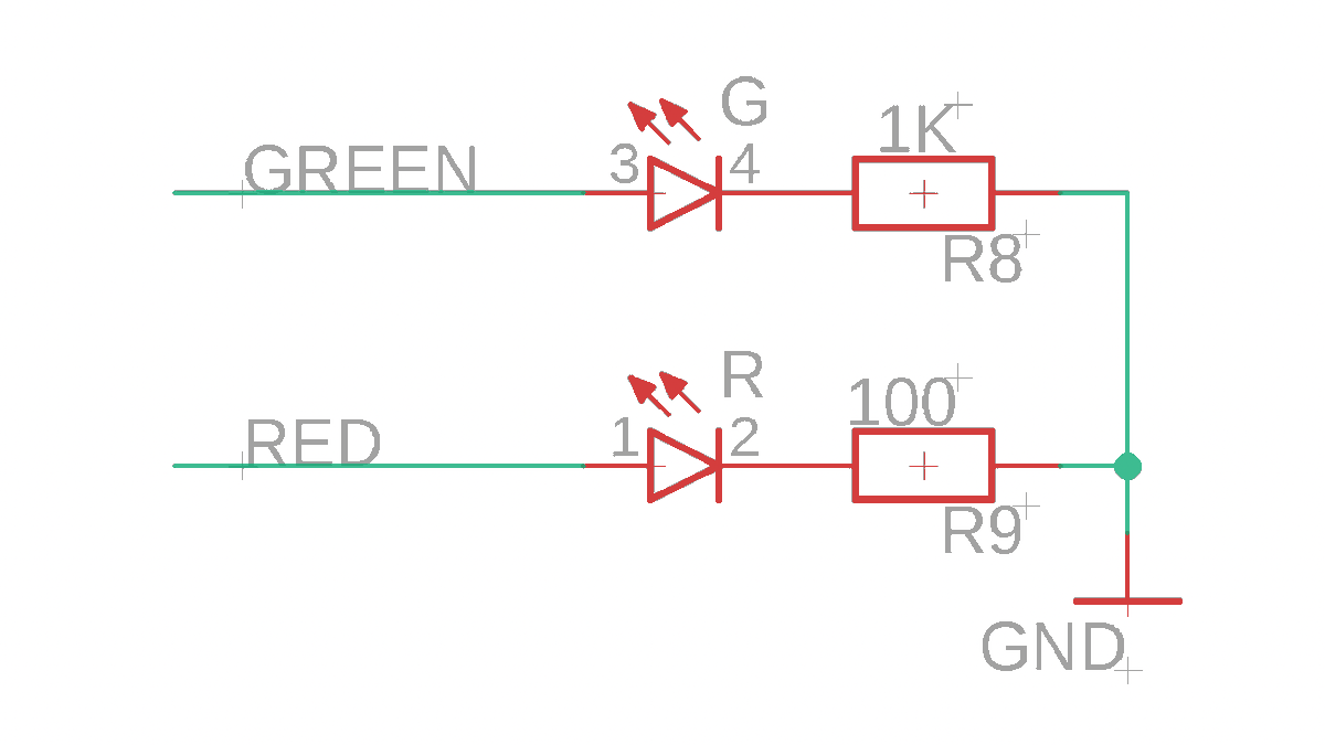
(original)
Replying to @josecastillo
This is actually a trick @adafruit does with their STEMMA boards (and one I learned from Desk of Ladyada a few months back): those green “On” LED’s? They’re current limited with 10K resistors, so they can do indicator duty while absolutely sipping power. https://youtu.be/oR7uGy8ea68?t=1206
(original)