Tweets
Replying to @josecastillo
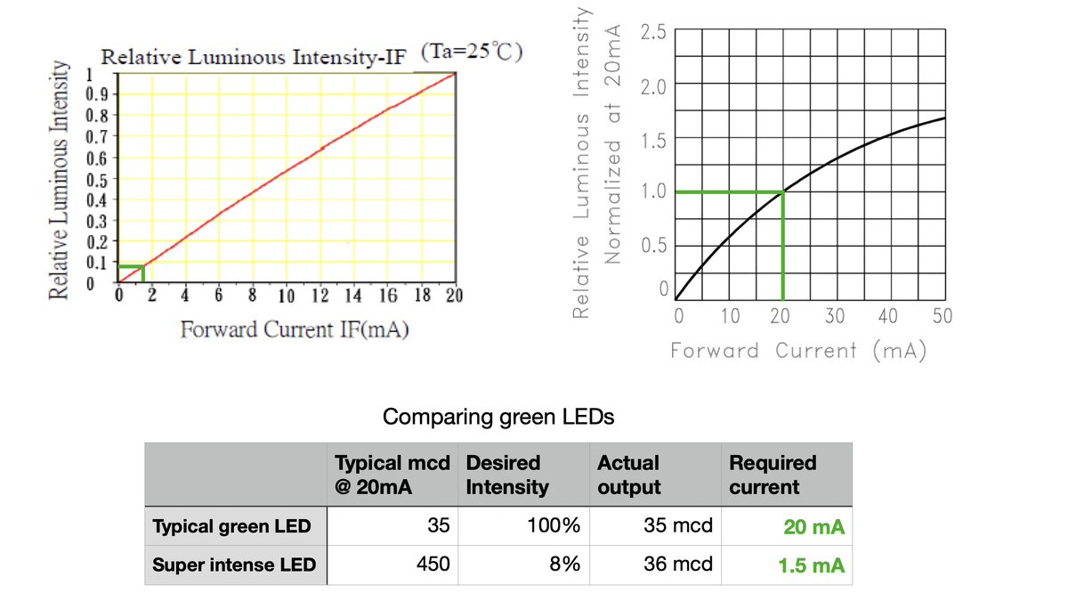
here’s the thing: you may want this for power reasons even if you don’t need eye-watering intensity. Let’s say you actually did want 35 millicandelas of output. You could feed 20 mA to your usual LED — or you could feed 1.5 mA to the super bright one. It’s more efficient!
(original)
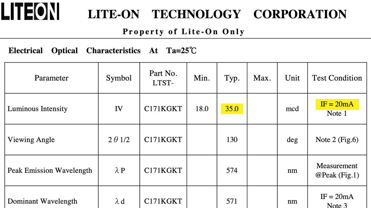
last night’s talk of low power got me thinking about the most power hungry part of the watch: LEDs. One interesting thing about the bicolor LED I’m using is the green is very bright. My usual green LED (below) maxes out at 35 millicandelas @ 20mA. this one hits 450 mcd. (thread!)
(original)
Replying to @mishkathebear
Three months to the day with display on and 1 Hz updates. But the data sheet suggests I can go far lower, even in standby mode. Gonna play with it some more this morning; there are a few flags in the power manager that I haven’t explored yet.
(original)
Replying to @matseng
I should write a thread on this. I was doing some math about it last night (getting ready for the red/blue LED that’s coming today) and I sense it would be useful knowledge to share. TL;DR though: it’s a high intensity LED driven at 5% of its maximum output.
(original)
Replying to @josecastillo
I also started from a starter project that used CR/LF endings which I’m sure are still lurking somewhere. but I don’t want to blow away the commit history over it, so there are just layers of cursed whitespace that I need to put out of my mind so I can focus on getting shit done.
(original)
side note: I indent my code with spaces. but for the watch, I’ve imported a lot of Atmel Studio library code that’s indented with tabs. wouldn’t be a big deal, except I’m changing that code a lot lately, which means I get to explore the dreaded Third Way.

(original)
Replying to @tactiZity_
could be documenting it more there, tbh. I should probably add these numbers to the software library documentation, so folks know the power impact of calling that function.
(original)
Replying to @fpgahelper
That is an great idea! I don’t know, but I will test that tomorrow when I’m in the shop. It wouldn’t be a mode for everyday use, but having the option to enter that mode and save power when unused would be a huge win.
(original)
Replying to @av1d508
I suppose you could also go dark at night (hours specified by the user) and wake up on an alarm in the morning; if the watch can deep sleep 8 hours a day, that increases its battery life by something like 33%, right?
(original)
Replying to @av1d508
You can use an alarm to wake, but BACKUP is most useful if the device is going to be unused for a long time. But with no ability to show text or get input unless you wake to STANDBY, you’d basically have to wake long enough to display “U there” & catch the user pressing a button.
(original)
Replying to @josecastillo
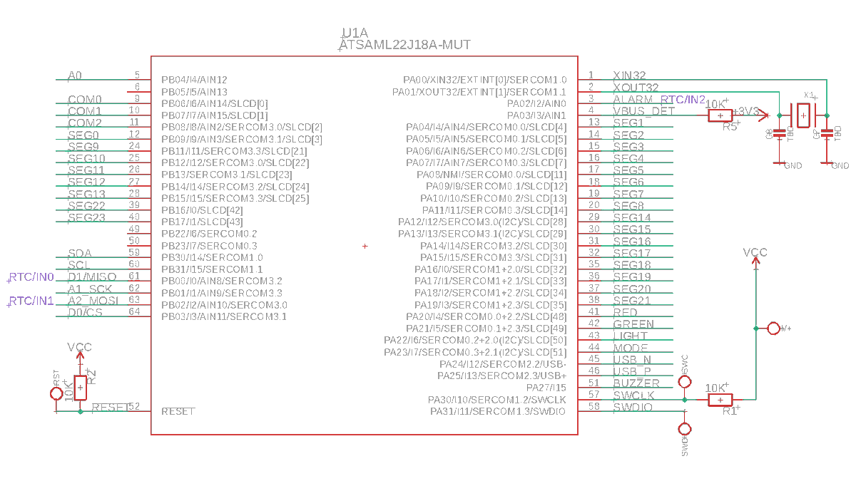
I’m not gonna do another spin of the board over it, that’s for sure; as of now, everything is in its right place. I can’t recruit PB00 or PB02 to the cause, since I need them for SERCOM3. and actually, the more I think about it, that’s the ball game if RTC/IN[2] is out of play :/
(original)
Replying to @josecastillo
if so, that’s a bummer. it means you can’t go into BACKUP mode and expect to come out of it without unscrewing the watch and hitting the reset button inside the case. That, or, adding a sensor board with a low power accelerometer that can wake on motion. Buttons may not cut it.
(original)
Replying to @josecastillo
UNFORTUNATELY, in my initial testing it seems the button on PA02 can’t wake the device from BACKUP mode. I’m able to wake it using the two pins on the 9-pin connector, but not the button. I think that bit of errata might imply there are only 2 external wake pins on the SAM L22 J.
(original)
Replying to @josecastillo
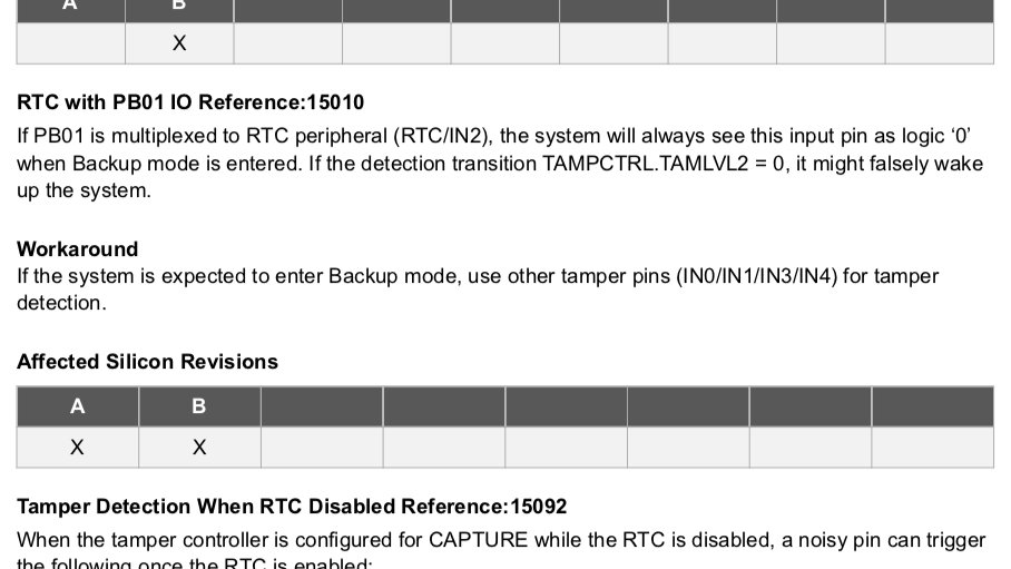
I used PA02 for this partly because I needed PB01 for its SERCOM capabilities, but also because there is a bit of chip errata on the RTC: when PB01 is mapped as an external wake input, it works in STANDBY, but not in BACKUP. I thought that using PA02 would work around this issue.
(original)
Replying to @josecastillo
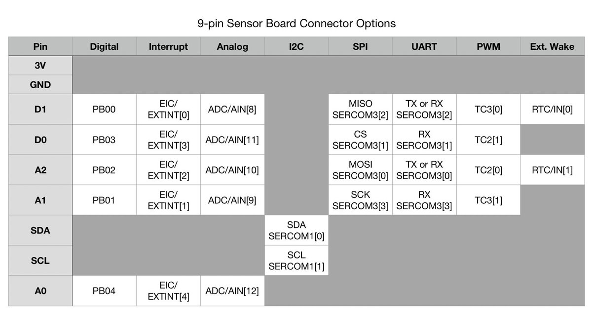
The J variant of the SAM L22 has three external wake pins:
* RTC/IN[0] on PB00
* RTC/IN[1] on PB02
* RTC/IN[2] on PB01 or PA02PB00 and PB02 are on the 9-pin connector; they’re part of SERCOM3, which is how the it can talk to an SPI device. I mapped PA02 to one of the buttons.
(original)
Replying to @josecastillo
Other modes: if running the CPU instead of hanging out in STANDBY, the baseline starts @ ~354µA. The interesting one is BACKUP mode, which goes down to just 15.6µA! The one caveat is that you can only wake from BACKUP with an alarm or external wake pin. And that may be a problem.
(original)
Spent some time with the power debugger today getting power numbers for the watch. TL;DW:
* Baseline case is STANDBY mode with RTC: 95 µA
* Add SLCD: +3-4 µA
* Update display @ 1Hz: +1 µA
* Red LED: +4500 µA (4.5 mA)
* Green LED: +440 µA (0.44 mA)
* Yellow LED: +4940 µA (4.94 mA)(original)
an artist friend once said he thought now that he was an adult, he could spend all his time making art. but instead it’s so much homework: proposals, budgets, responding to emails. just something that came to mind as I stare at this spreadsheet of part numbers and component costs
(original)
Replying to @josecastillo
I’m working on the manufacturing piece today; the one hiccup is that my red/green LED is currently unobtanium. But! I just ordered a red/blue LED with the same footprint for testing; if it works, swapping two resistors should give me an alternate version with bisexual lighting :)
(original)
ICYMI: The Sensor Watch got a lovely writeup on @hackaday yesterday!
“It’s got that classic Casio look of a segment LCD display… but the added bonus is that we know these have decent water resistance while still providing three buttons for user input.” https://hackaday.com/2021/08/08/wristwatch-pcb-swaps-must-be-in-the-air/(original)
Sunday watch progress: got the buzzer working. And it’s no johnny one-note. I included definitions for 108 tones, including sharps and flats. This demo displays the position in the song and the period each note is setting in the PWM driver. https://github.com/joeycastillo/Sensor-Watch/commit/616e4fb1054fb2d500e4720a38b02501c8214030#diff-2dd43d038bb386971d7a77e852bc502f363c8b5b0e09c95d7467554c4c2a0e14R220
(original)
Replying to @trufae
So far the first battery life test lasted 3 months, updating the screen once a second, but it could go longer; I am still working on the firmware. There may be motion on the emulation front shortly; watch this space!
(original)
Replying to @LeviMaaia
I’m working on figuring out the manufacturing piece, also chasing down one last issue with the USB port that folks will use to program the watch; waiting on some boards that are stuck in customs. Stay tuned, I hope to have this figured out in the coming weeks! /cc @MajorBitTie
(original)
Replying to @theavalkyrie
I appreciate seeing that even if you made mistakes, you can bodge a wire, get some value from a prototype, and learn lessons that make the next revision better. If everything I made had to be perfect I’d never make (or learn!) anything.
(original)
Replying to @songsteven2
Felt right!
(original)
Replying to @josecastillo
You have to do the work. Chasing ideas is fun. But in focusing on this gadget I’ve done five revisions, written lots of code, placed parts with tweezers, spent hours staring at intractable bugs. Sometimes doing the work is repetitive. But the work won’t get done unless you do it.
(original)
Replying to @josecastillo
Maybe there are two other lessons actually. There are several things in here where an idea seemed quixotic but I chased it anyway. Maybe it worked out, maybe it didn’t. Either way I learned something. Sometimes that thing proved useful later! But the bigger process thing is this:
(original)
Replying to @josecastillo
Mostly tho I feel fortunate to have support from a community, both online & IRL. I didn’t build this alone. 18 months ago I didn’t know half the things I needed to know to make this work. I learned from folks sharing their knowledge freely. That’s a good process; more of that :)
(original)
Replying to @josecastillo
Anyway. I’m not sure if this thread covers something that fulfills the question of “process”, except inasmuch as a process is a thing you do, and these are things I did that led to this object. Failed a lot; learned fast. Borrowed ideas; shared alike; shouted out my inspirations.
(original)
Replying to @josecastillo
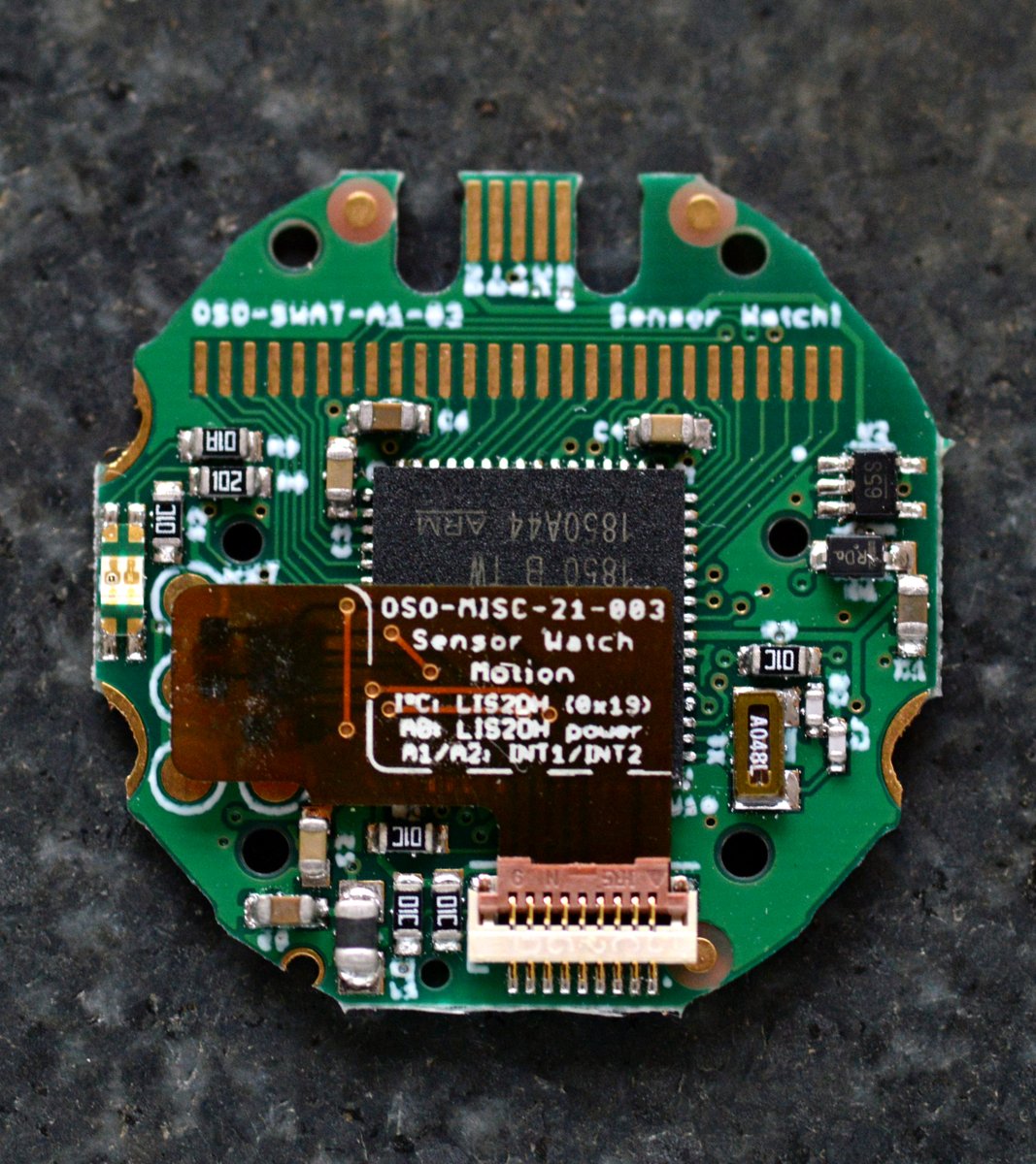
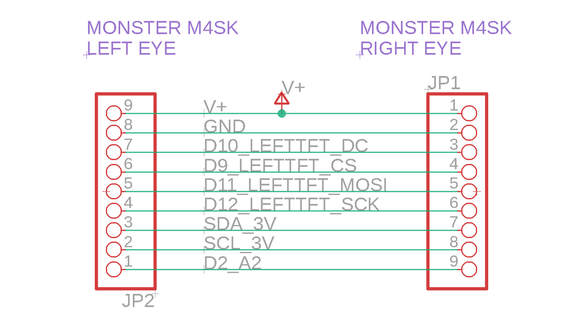
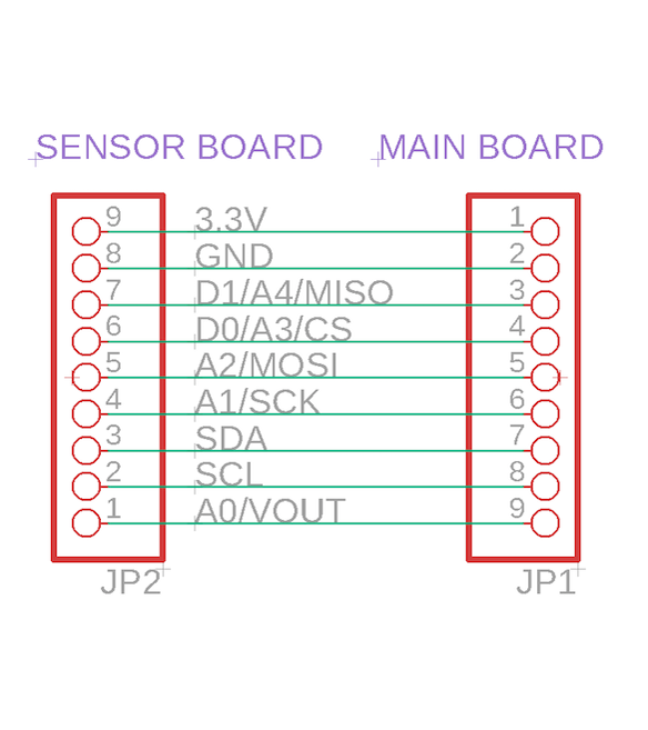
I’ve cribbed so many ideas for this from other smart people, and it builds on ideas I’ve been hacking on for over a year. The 9-pin connector has changed forms, but the pinout? That’s all MONSTER M4SK. This design builds on a foundation I’m not even sure we knew we were building.
(original)
Replying to @josecastillo
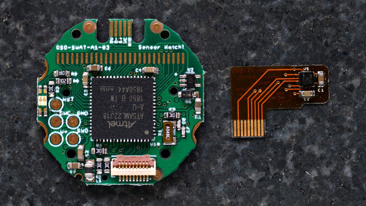
This is the current version. I’m still chasing down one last issue with USB reliability; waiting on one more prototype which I hope to assemble next week. The gadget has reached what I think is a pretty high level of maturity at eight months old. Then again, it’s older than that.
(original)
Replying to @josecastillo
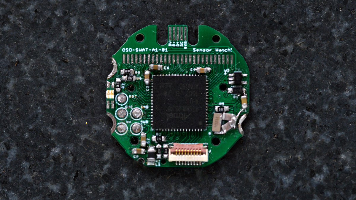
This was the third prototype. Had to order from overseas to get it in 0.6mm thickness which was required for the USB connector (and to fit in the watch case). Aside from the obvious bodge of missing load capacitors, the placement here is basically what it is in the current watch.
(original)
Replying to @josecastillo
I addressed the issues. Fixed my LCD pin muxing. Added a 3.3V regulator (for use when plugged in to USB). Fourteen days later I had another prototype in hand. And even at that point, a third prototype was getting made at a factory in Shenzhen… https://twitter.com/josecastillo/status/1357518204965380097
(original)
Replying to @josecastillo
Actually working on the hardware let me learn lessons quickly. I screwed up some of the LCD pin muxing, for example. But even with those mistakes, I was able to learn things. Like some of the quirky things the F-91W does with its segment LCD layout: https://twitter.com/josecastillo/status/1353475467144278017
(original)
Replying to @josecastillo
I ordered this first version from @oshpark on a quick turn, just to start hacking on firmware and get a sense for working with a new chip. This bit is incredible: for $10 I was able to go from idea to hardware to writing code in a week and a half. Amazing! https://twitter.com/josecastillo/status/1352459044460654594
(original)
Replying to @josecastillo
The Sensor Watch started on a lark. @GregDavill had designed a SAM L22 calculator watch the month before. I loved the idea. A watch is bigger than a ring, but it’s eminently wearable. I chose to target the iconic F-91W. Same nine-pin connector, of course. https://twitter.com/josecastillo/status/1348474279952855044
(original)
Replying to @josecastillo
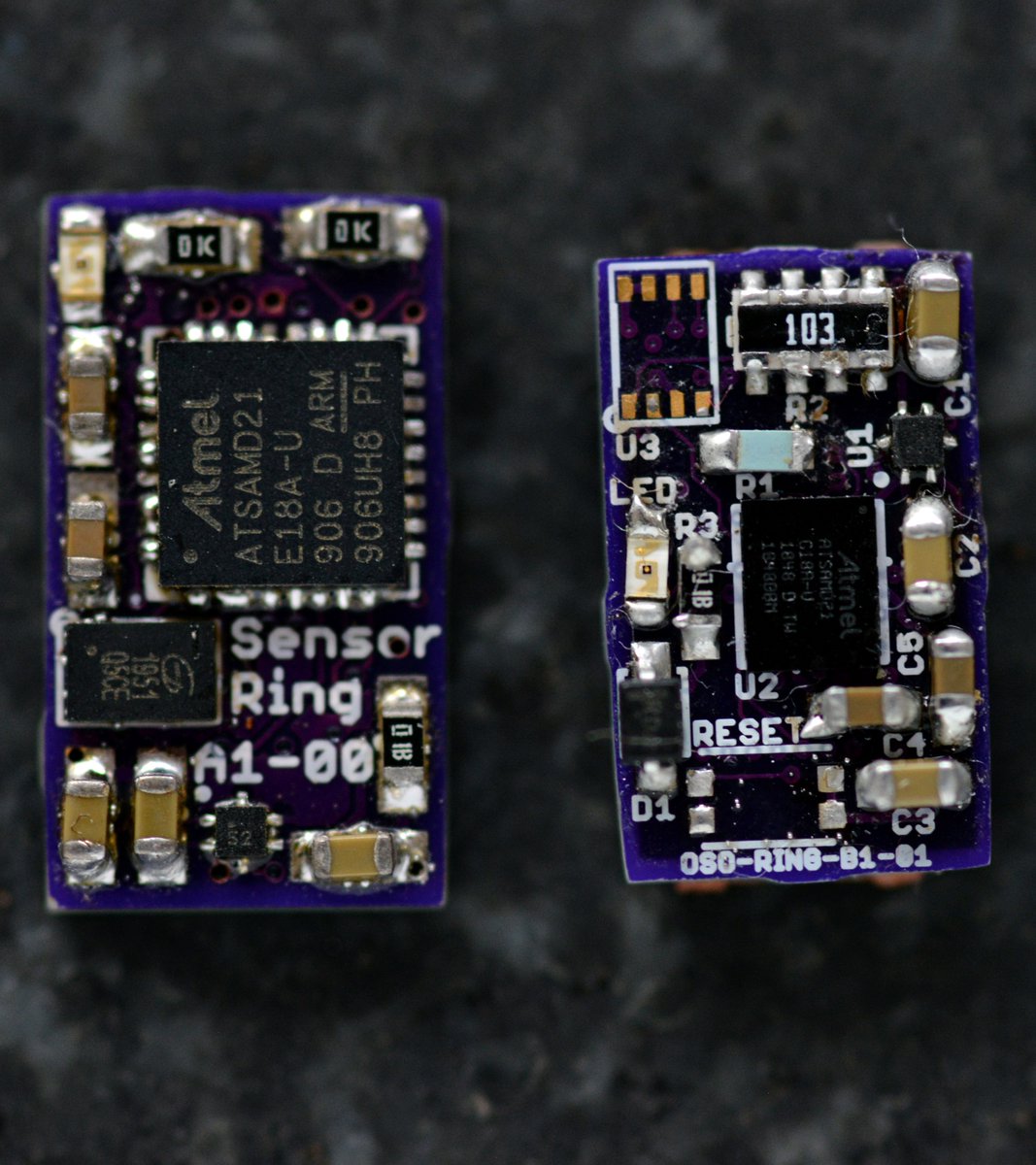
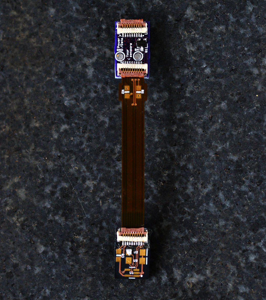
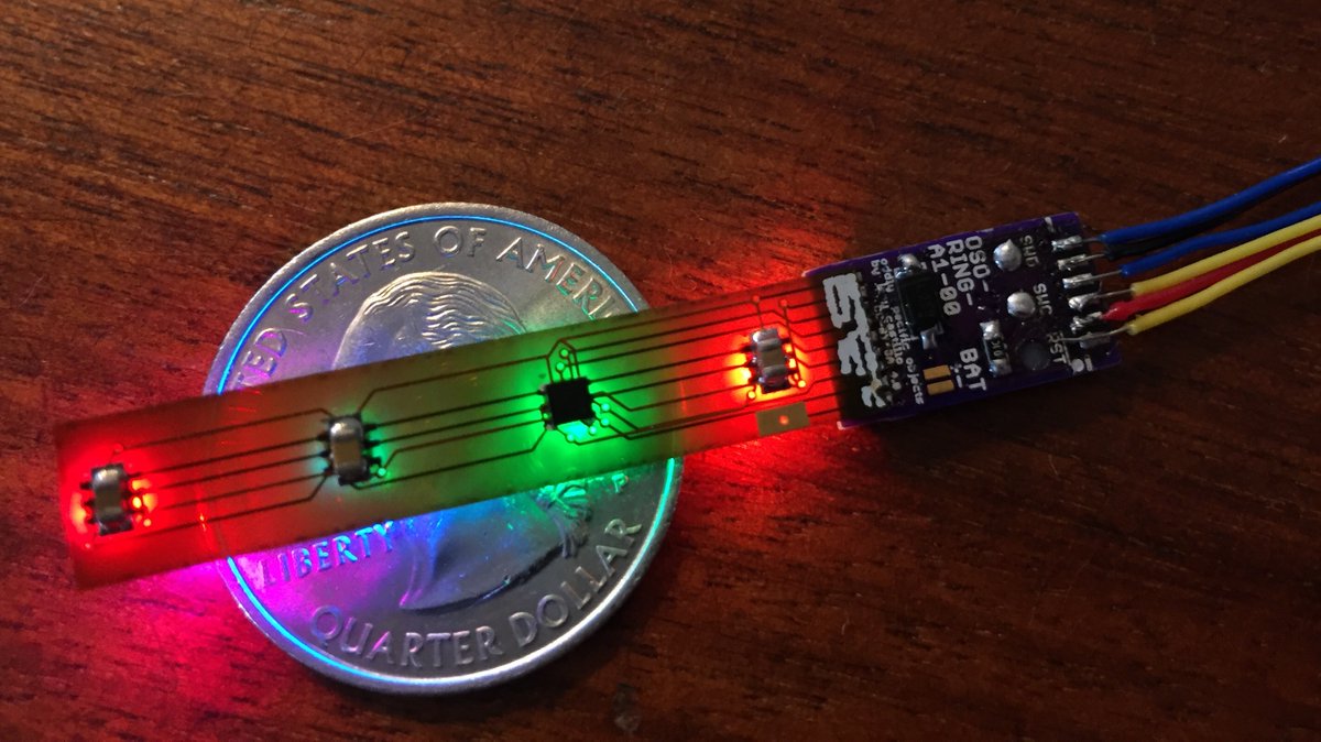
Now it’s December. Sensor Ring v2 aimed to go EVEN SMALLER, and fix the fragility issue by using a 9-pin flex PCB connector. This would have been a heart rate sensor, but for the fact that I made mistakes on both of these designs. Besides, by January I was working on a new thing.
(original)
Replying to @josecastillo
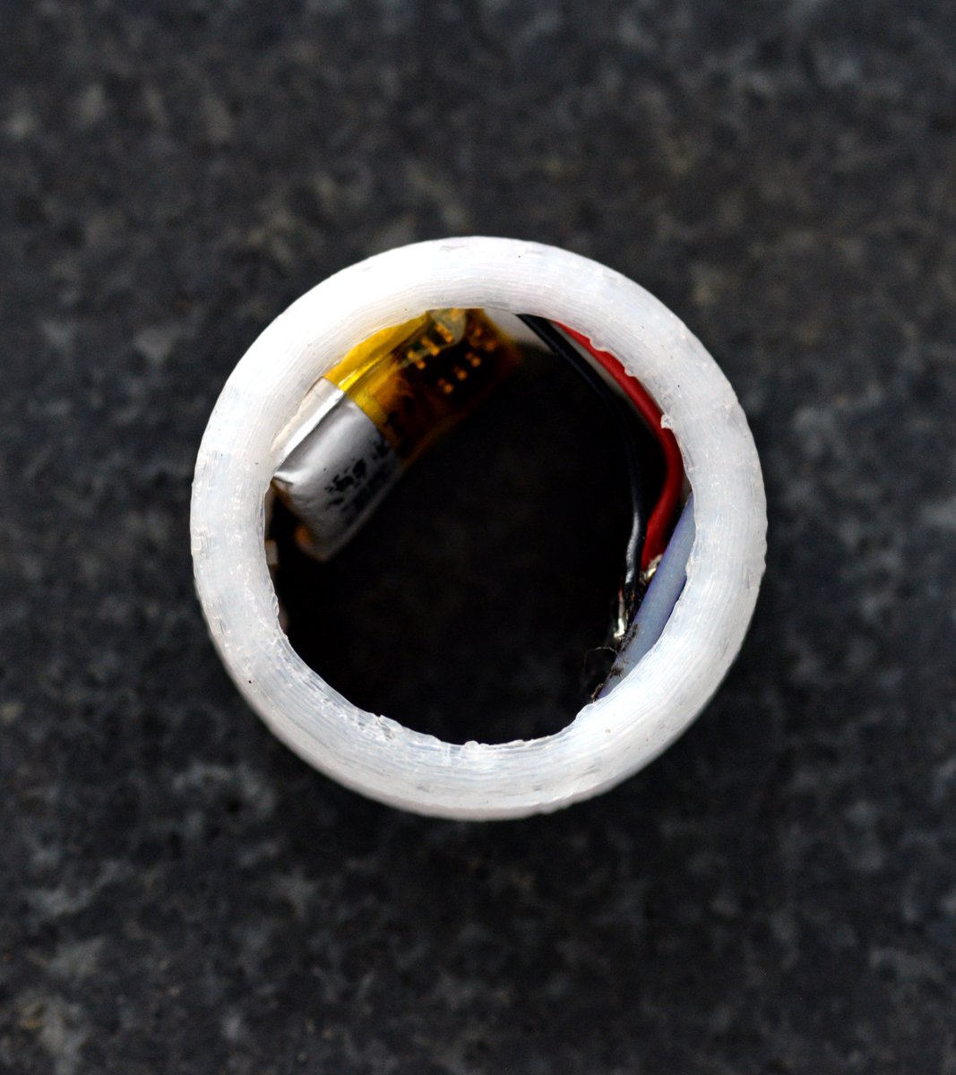
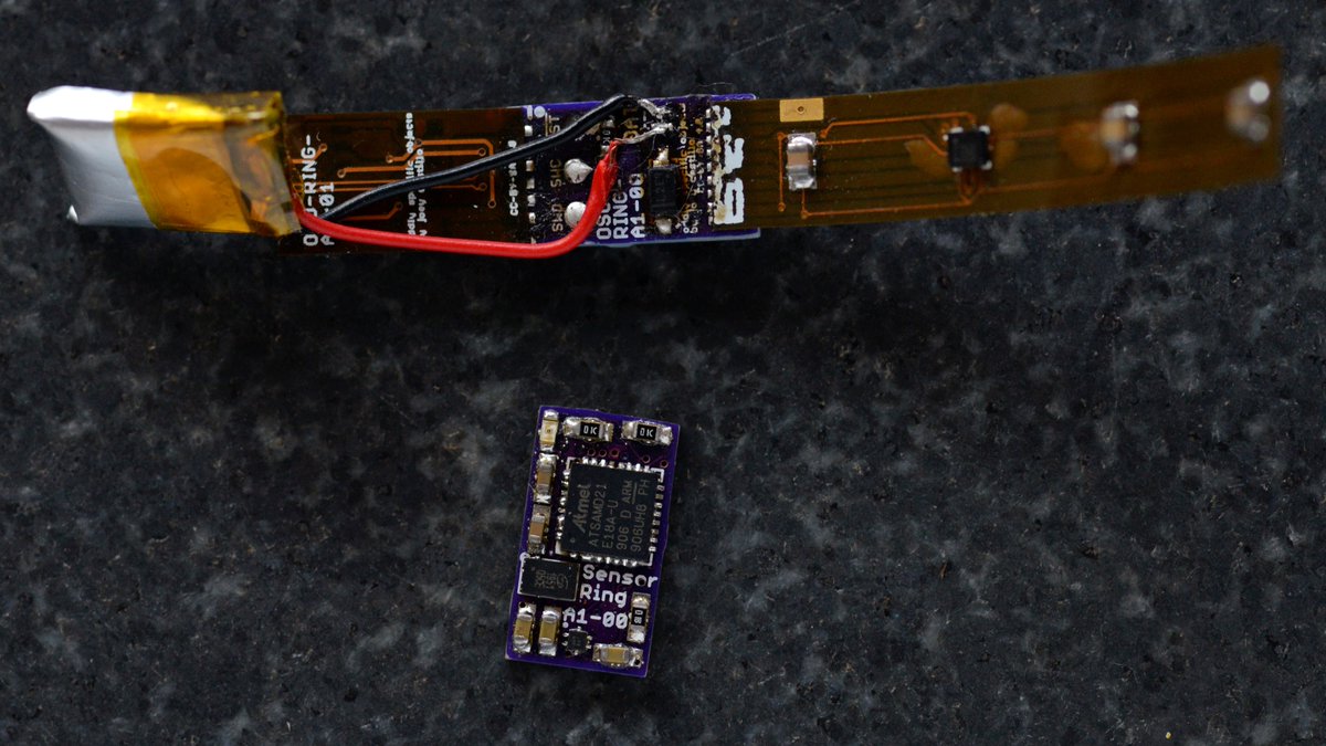
There were of course other issues with this design, not least of which: it’s probably not wise to place a lithium polymer battery in a tight enclosure directly against your skin. Still, it gave good demo, and it did mostly work, at least for a while.
(original)
Replying to @josecastillo
By October, I’d decided I wanted to go smaller. Enter the Sensor Ring. This probably takes the title for smallest @CircuitPython board on earth. And of course I used the same nine-pin pinout, except this time, you soldered a flex PCB directly to nine pads on the back. (fragile!)
(original)
Replying to @josecastillo
There was also a tiny version of the Open Book (the Tiny Book, of course) that included the nine-pin connector as an option for adding a second screen. Again, largely the same pinout, so that I could keep using it with those little sensor boards I’d made. https://twitter.com/josecastillo/status/1299369843695722496
(original)
Replying to @josecastillo
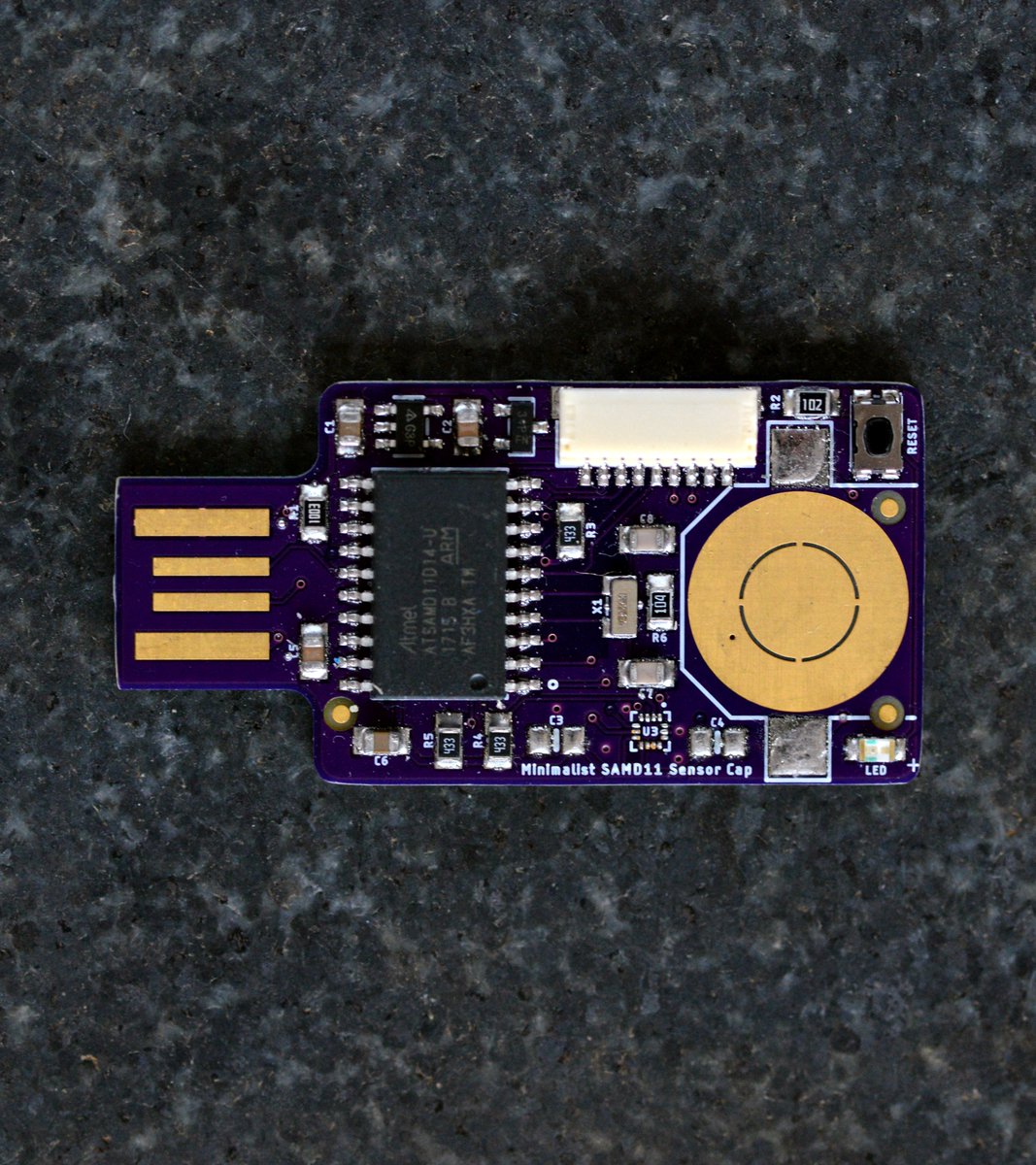
That takes us to May of last year. By this time I’d designed several “sensor boards” that used this nine-pin connector. So I kept designing gadgets to work with them. Here’s a thread with the “Sensor Candle”, a SAM D11 board powered by a CR2032 coin cell: https://twitter.com/josecastillo/status/1288836416055762945
(original)
Replying to @josecastillo
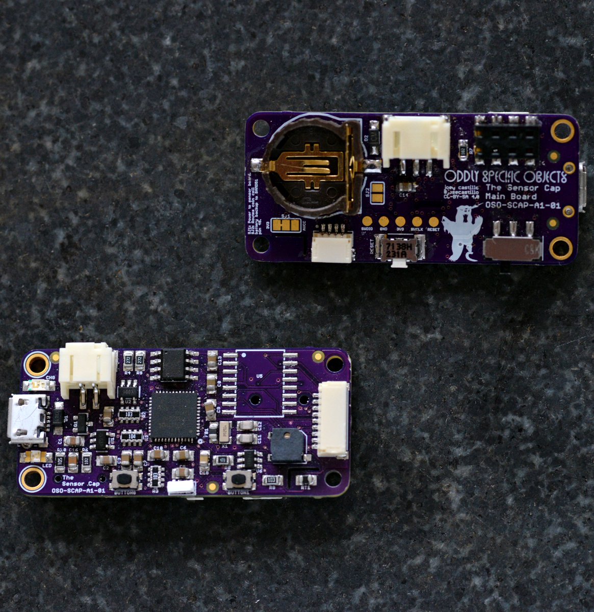
There were some issues with that first one, but the nine-pin concept seemed sound. So I made a second and a third one: a SAM D51 based version with a Cortex M4, and a simpler SAM D11 version powered by coin cell. That one logged small amounts of data to an EEPROM emulation area.
(original)
Replying to @josecastillo
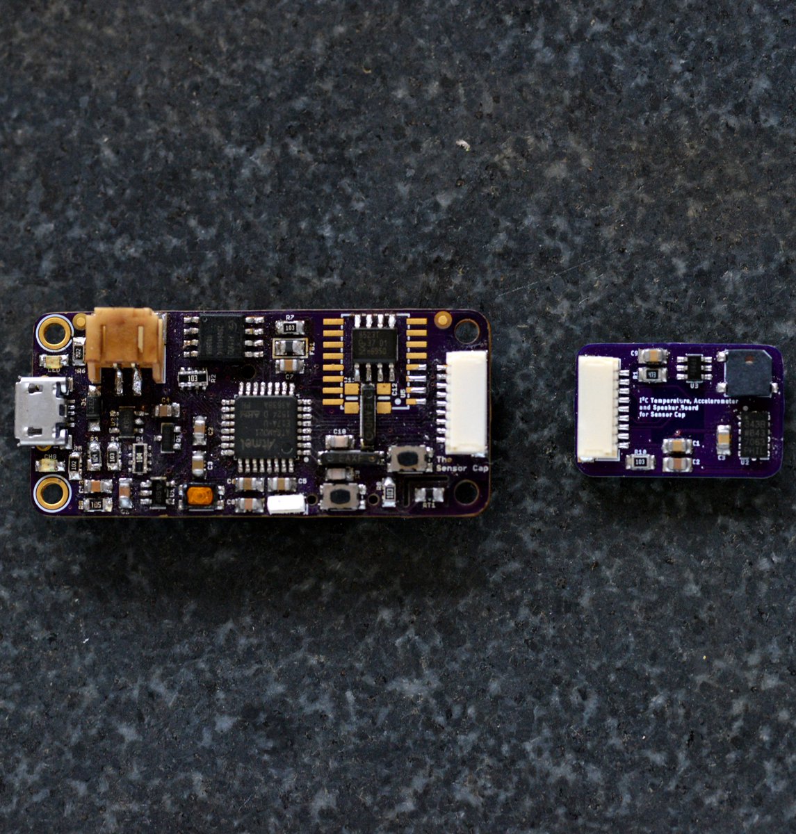
This was the first iteration of the Sensor Cap. I cribbed the 9-pin connector from @Adafruit’s MONSTER M4SK. They use it to connect a screen and an I2C interface from one eye to the other; I kept to a very similar pinout, and used it to hook up some sensors and a tiny speaker.
(original)
Replying to @josecastillo
Pretty quickly I realized that while the Feather was a great small form factor, it still felt a bit bulky when attached to my forehead. So I started designing a board with the same shape, but with a nine pin JST-SH connector for interfacing with sensors. https://twitter.com/josecastillo/status/1243349759366217729
(original)
Replying to @josecastillo
The story begins in March of 2020, the beginning of the pandemic. I’d just fled from New York to Texas, and in quarantine, I thought continuous temperature sensing could be a useful technology. So I put a Feather with a temperature sensor in a baseball cap https://twitter.com/josecastillo/status/1240439026282385409
(original)
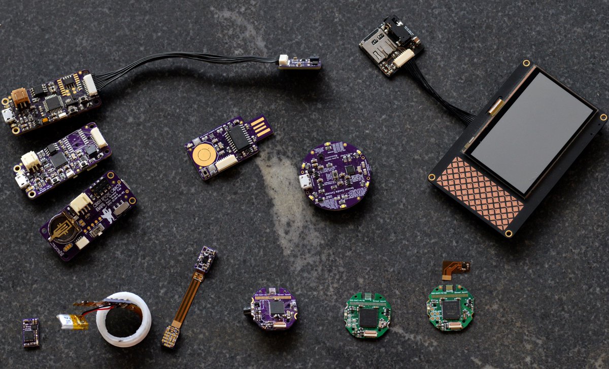
Yesterday @falconsview asked if I had a writeup of my process for the watch and it occurred to me: it’s an interesting story. It traces back a year and a half, through a menagerie of gadgets. I was even able to gather some for a family portrait! Join me in a retrospective THREAD:
(original)
Replying to @gameduino and @Magic_CAD
That would be very welcome! And let me know if there’s anything I can do to the codebase to make it more compatible with that kind of effort; I’m very open to ideas and improvements.
(original)
Replying to @gameduino and @Magic_CAD
I had that fear a few months ago… I bought a partial reel of 110 and I’m hanging on to them to hopefully do a small run, but yeah after that it’s going to be slim pickings :/
(original)
Replying to @Magic_CAD
It does, but I need to write a UI for setting the time on the device. Not that much work but something I need to get to. Small steps; just gotta keep doing the work.
(original)
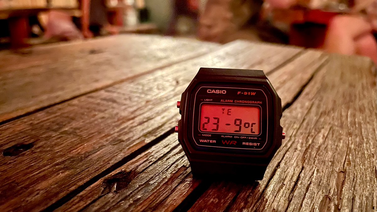
took the watch out to (outdoor) drinks with the shopmates. My weather app predicted 25° C, but I’ll take 23.9°. Either way, a perfect late summer night.
(original)